


WE ARE THE WORLD’S LEADING TEC MODULE SUPPLIER WITH THE MOST COMPLETE SERIES AND LARGEST STOCKING INVENTORY.
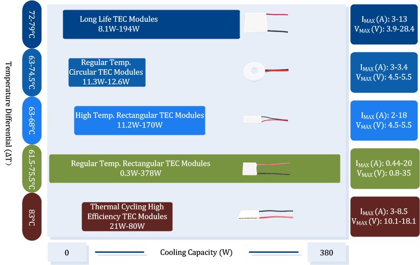
Analog Technologies offers single-stage Peltier modules in five categories — Regular Temperature Rectangular, High Temperature Rectangular, Regular Temperature Circular, Thermal Cycling (Long Life), and Thermal Cycling High Efficiency — covering 20+ series, from 7 to 288 couples. RoHS and REACH compliant, stocked for immediate shipment in both sealed and non-sealed variants.
Main Features
Single-stage Peltier modules with the most complete series (ATE1-XX, ATE1-TC, ATE1-TCHE, ATEC1-XX) and largest stocking inventory. Used in laser diode cooling, PCR instruments, CCD / IR detectors, sensor thermal management, and industrial temperature regulation. — Since 1997.
Documentation & Compliance
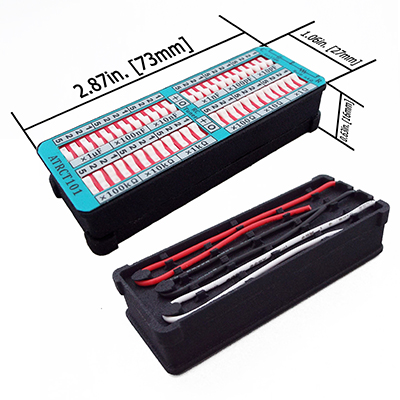
Selection Guides & Price Lists 5
Regular Temperature Rectangular
ATE1-XX series. 135 °C internal solder, 125 °C max surface. Largest product family with 13 series.
View Guide & Price List → High TempHigh Temperature Rectangular
−H suffix parts. 238 °C solder / 200 °C operation for high-ambient industrial cooling.
View Guide & Price List → CircularRegular Temperature Circular
ATEC1-XX round modules. For TO-can laser diodes, photodetectors and circular optical sub-assemblies.
View Guide & Price List → Long LifeThermal Cycling (Long Life)
ATE1-TC series. Withstands up to 20,000 full-scale current reversals. Ideal for PCR thermal cyclers.
View Guide & Price List → High COPThermal Cycling High Efficiency
ATE1-TCHE series. Long-life thermal cycling plus improved Coefficient of Performance for PCR / bio-instruments.
View Guide & Price List →

Click any series below to download its full specifications PDF. Each datasheet covers all variants within that series — sealed / non-sealed, multiple current ratings, and where applicable high-temperature (−H suffix) versions. Series that appear in multiple Selection Guides (see the 5 category cards above) are listed in each relevant category below. For low-volume specialty ΔT modules (ATE1-08, 11, 32, 65 rectangular variants), see our High ΔT TEC Modules datasheet.
Regular Temperature Rectangular 13 datasheets View Guide
The largest family, covering 7 to 288 couples. 135 °C internal solder, 125 °C maximum surface temperature. General-purpose single-stage Peltier modules for laser diode cooling, CCD / CMOS sensors, IR detectors, and standard industrial thermal management.
- ATE1-07 Series TEC Modules
- ATE1-17 Series TEC Modules
- ATE1-18 Series TEC Modules
- ATE1-31 Series TEC Modules
- ATE1-35 Series TEC Modules
- ATE1-49 Series TEC Modules
- ATE1-63 Series TEC Modules
- ATE1-71 Series TEC Modules
- ATE1-127 Series TEC Modules
- ATE1-161 Series TEC Modules
- ATE1-199 Series TEC Modules
- ATE1-241 Series TEC Modules
- ATE1-288 Series TEC Modules
High Temperature Rectangular 4 datasheets View Guide
Rectangular TEC modules with 238 °C internal solder, rated for operation up to 200 °C. For high-ambient industrial cooling, heated-bath instruments, and applications where the heat sink surface exceeds the 125 °C limit of Regular Temperature modules. Parts end in an −H suffix; each datasheet covers both the −H variants and the corresponding Regular Temperature versions where they exist.
Regular Temperature Circular 2 datasheets View Guide
Round TEC modules with a center through-hole, sized to fit TO-can laser diodes, photodetectors, and circular optical sub-assemblies. Same 125 °C maximum surface temperature as Regular Temperature Rectangular; the donut form factor lets heat flow through a central beam path without blocking it.
Thermal Cycling (Long Life) 4 datasheets View Guide
Long-life TEC modules engineered for repeated full-scale current reversals — up to 20,000 cycles before ACR rises 10 %, roughly 20× the life of a standard TEC. The preferred choice for PCR thermal cyclers and any instrument that switches TEC polarity frequently.
Thermal Cycling High Efficiency 4 datasheets View Guide
Combines the 20,000-cycle long life of the TC series with an improved Coefficient of Performance (COP). Use these when both long life and energy efficiency matter — typical in battery-powered or large-scale bio-instruments.
What Are TEC Modules?
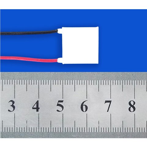
Thermoelectric coolers (TECs) — also known as Peltier coolers, thermoelectric modules, or TEC modules — are solid-state devices that generate both heating and cooling by applying a DC current. When current flows in one direction, one Peltier ceramic plate heats up while the opposite plate cools down; reversing the current swaps the hot and cold sides. TEC modules are widely used for precision temperature regulation of laser diode chips to maintain a stable emission wavelength with minimal optical noise, and for cooling CCD / CMOS image sensors, IR detectors, PCR wells, medical instruments, and compact portable refrigeration.
How to Select the Right TEC Module
When designing a temperature regulation system based on TECs, the following engineering checklist helps narrow the right series quickly:
1. TEC Lifespan & ACR (AC Resistance)
TECs have a finite lifespan, measured by the relative rise of their AC resistance. An ACR increase of 10 % marks end of useful life. ACR rises because the internal semiconductor (Peltier) elements expand and contract with thermal cycling, producing micro-cracks. Standard TECs withstand roughly 1,000 full-scale current reversals; Analog Technologies long-life TECs (ATE1-TC / ATE1-TCHE series) withstand up to 20,000. For PCR and any application with frequent full-scale reversal, always pick the long-life series.
2. ACR Measurement
ACR must be measured with a dedicated LCR meter — regular multimeters only read DC resistance. Pre-screening TECs by initial ACR is critical for building long-lasting systems; burn-in services are also available on request.
3. Minimize ΔT to Maximize COP
System efficiency (Coefficient of Performance, COP) rises as the hot-to-cold temperature difference ΔT falls. Use a sufficiently large heat sink — add a cooling fan if needed — to keep ΔT < 30 °C and reach COP > 1 or 2. Refer to the TEC module datasheets for specific ΔT / Qmax curves.
4. Avoid Shear Force
TEC modules tolerate high compressive force (typically 25–100 psi) but are vulnerable to shear stress, which cracks the internal Peltier elements. Design mechanical fixtures accordingly.
5. Gentle Current Switching
Avoid hard on/off switching. A smoothed, slow-varying DC drive is optimal. If using PWM, keep the PWM frequency ≥ 1 kHz — higher is better for the TEC, though driver efficiency may fall.
6. Mounting Method Selection
Three common methods: compression with thermal grease, adhesive bonding, and soldering. Use compression for large assemblies (≥ 30 mm × 30 mm) — most cost-effective and shear-tolerant. Use adhesive bonding for small assemblies (≤ 20 mm × 20 mm) such as laser diode coolers. Use soldering for the highest thermal performance on small, long-life assemblies where mechanical shock can be controlled. Contact us for free mounting-design consultations.
Frequently Asked Questions
- Q1. How do I identify the cold side and the positive lead of a TEC module?
- When mounting, attach the side with the soldered lead wires to the heat sink — that side becomes the hot side, and the opposite face becomes the cold side on which the target object is mounted. The positive terminal is defined such that, when connected to the positive of a DC supply, the pre-defined cold side cools down.
- Q2. What is the life expectancy of a TEC module and how is it determined?
- Life is defined as the point at which ACR (AC resistance) has risen by 10 %, measured by an LCR meter. Applying the full maximum voltage with reversed polarity accelerates ageing. Standard TECs survive up to about 500–1,000 such reversals; Analog Technologies long-life TECs survive up to 20,000. Calculated MTBF is about 125,000 hours.
- Q3. What is the difference between TEC modules and TEG modules?
- TEC = Thermo-Electric Cooler: apply current → get a hot and a cold side (Peltier effect). TEG = Thermo-Electric Generator: apply a temperature difference → get a voltage that drives a load (Seebeck effect). Both use similar semiconductor elements but are optimised for opposite directions of energy conversion.
- Q4. Which TEC series should I use for a laser diode?
- For small laser diode submounts use a low-couple-count Regular Temperature Rectangular series (ATE1-07, ATE1-17, ATE1-18), typically attached by adhesive bonding, or a Regular Temperature Circular (ATEC1-) module for TO-can packages. For higher optical power use ATE1-31, ATE1-49 or ATE1-71. If your driver frequently reverses full-scale current, pick ATE1-TC or ATE1-TCHE.
- Q5. Which TEC is recommended for PCR / thermal-cycling instruments?
- Use the long-life thermal-cycling series — ATE1-TC-31, ATE1-TC-71, ATE1-TC-127, ATE1-TC-199 — or the higher-COP ATE1-TCHE-31, ATE1-TCHE-32, ATE1-TCHE-71, ATE1-TCHE-127 modules. They withstand up to 20,000 full-scale current reversals before ACR rises 10 %, versus roughly 1,000 for Regular Temperature Rectangular TECs.
Handling TEC Modules Properly
TECs are fragile; the following engineering practices maximise service life:
A. Do not drop or mechanically shock the module — invisible micro-cracks in the Peltier elements will shorten life. Check by measuring ACR: a rising ACR indicates damage.
B. Measure ACR only with a proper LCR meter. DC multimeters do not reveal Peltier-element cracking.
C. For long-life systems start with a low initial ACR part. Analog Technologies provides pre-screening by initial ACR and optional burn-in so that every delivered module has demonstrated long-life performance.