AI accelerators concentrate intense heat into tiny die areas — but unlike laser diodes or imaging sensors, many of them can run at a noticeably higher controlled temperature. That difference is a quiet design opening. ATI's high-temperature TEC modules are rated to 200 °C maximum surface temperature, versus 125 °C for regular TEC modules. With the same heat sink and airflow at room ambient, that's roughly 2× the heat-sink-to-ambient driving force and about +30% theoretical no-load ΔT_max — enough headroom to fit more compute behind the same or a smaller heat sink.
Think of the heat sink as a highway carrying heat to ambient air. Letting it run hotter widens the temperature drop to ambient — like opening more lanes for heat to leave without enlarging the highway itself.
• +75 °C of raw ceiling — maximum operating surface temperature moves from 125 °C to 200 °C, before any reliability margin is reserved.
• The headroom survives margin — after a conservative 25 °C solder/reliability margin, the practical hot-side design point still rises from 100 °C to 175 °C.
• ≈2× heat-rejection driving force — at 25 °C ambient, heat-sink-to-ambient ΔT grows from 75 °C to 150 °C for the same fins and airflow.
• ≈+30% theoretical no-load ΔT_max — from ≈96 °C at T_h = 100 °C to ≈125–126 °C at T_h = 175 °C.
• Headroom traded for density, cost, or noise — a smaller, cheaper, or slower-fan heat sink frees space for compute, power delivery, and packaging.
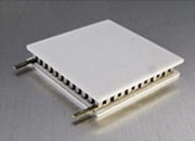
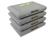
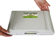
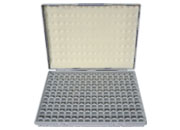
It uses the same compact footprints engineers already specify — ATE1-19, ATE1-35, ATE1-71, and ATE1-127 — so the mechanical design changes very little. What changes is the temperature ceiling.
Same ambient, same heat-sink size, same airflow. Heat rejection estimated by the first-order relation Q_hs ≈ (T_hs − T_amb) / R_θ.
| Parameter | Regular TEC | ATI high-temperature TEC | Implication |
|---|---|---|---|
| Max TEC surface temperature | 125 °C | 200 °C | +75 °C ceiling |
| Practical hot-side temp (after 25 °C margin) | 100 °C | 175 °C | +75 °C headroom |
| Heat-sink-to-ambient ΔT (25 °C ambient) | 75 °C | 150 °C | 2.0× driving force |
| Heat-dumping power, same heat sink | 100% | ≈200% | ≈+100% (first-order) |
| Theoretical no-load ΔT_max | ≈96 °C @ T_h=100 °C | ≈125–126 °C @ T_h=175 °C | ≈+30% |
| Heat-sink requirement, same load | 100% | ≈50% | up to ≈50% smaller, before margin |
First-order engineering estimate. Real heat-sink performance also depends on airflow, fin geometry, orientation, fan curve, ducting, radiation, dust, mounting flatness, TIM quality, and enclosure effects.
ΔT_max is not a fixed constant — it tracks hot-side temperature T_h. Lift T_h and the theoretical no-load ΔT_max rises with it:
ΔT_max(T_h) = T_h + 1/Z − √(2·T_h/Z + 1/Z²)
with T_h in kelvin and Z the module figure of merit (here Z ≈ 2.5×10⁻³ /K, i.e. 1/Z = 400 K, calibrated to the datasheet baseline). For an ATE1-127-class module rated ≈66 °C at T_h = 27 °C, this gives ≈96 °C at T_h = 100 °C and ≈125–126 °C at T_h = 175 °C. These are no-load values, not guaranteed capacity under load.
Engineering caution: a higher theoretical ΔT_max is not a reason to run the TEC as hot as possible. Elevated temperature also raises material stress and reliability risk. Reach for the high-temperature series when the application needs the headroom — and apply normal derating and lifetime checks either way.
Use it when the controlled device can safely sit at an elevated setpoint and you want to push more heat through a smaller, quieter, or simpler thermal path: AI data center GPU and accelerator hot-spot cooling; high-power ASIC, processor, and IC thermal management; power electronics and hot-spot spreading; industrial electronics in elevated-ambient enclosures; automotive, aerospace, and defense electronics; and semiconductor process equipment.
What is a high-temperature TEC module? A thermoelectric cooler designed for a higher allowable hot-side/surface temperature than a regular module — ATI's are rated to ≈200 °C versus ≈125 °C.
Why is it useful for AI GPU cooling? GPUs run hot but tolerate elevated controlled temperatures, so the heat sink can follow them up — growing heat-sink-to-ambient ΔT and improving rejection for the same heat sink and airflow.
Does a hotter heat sink always increase cooling capacity? No. It improves rejection and lifts theoretical no-load ΔT_max, but actual capacity under load still depends on Q_c, TEC current/voltage, TIM quality, heat-sink resistance, and derating.
Can the heat sink really shrink by ~50%? As a first-order estimate, yes — doubling the driving force from 75 °C to 150 °C lets the same load use a heat sink with roughly half the thermal capability, before margin. Verify airflow, fin geometry, fan curve, aging, and enclosure effects.
ΔT_max vs. heat-sink-to-ambient ΔT — what's the difference? ΔT_max is the max no-load difference across the TEC itself (T_h − T_c). Heat-sink-to-ambient ΔT is between the heat sink and the air. They sit in different parts of the thermal network and must not be interchanged.
Related: High-Temperature Rectangular TEC Selection Guide · TEC Modules · ATE1-19 · ATE1-35 · ATE1-71 · ATE1-127 · TEC Controllers · Heat Sinks · White Papers · Contact