Switching power supply can be divided into isolation and non-isolation circuit. In this paper, we will focus on the non-isolation circuit. According to different circuit forms, it can be divided into buck circuit, boost circuit, buck-boost circuit, cuk circuit, sepic circuit and zeta circuit. Here, we mainly analyze the working principle of
DC-DC step down converter circuit. As shown in figure 1, power MOSFET is an adjusting switch element and its turn-on and turn-off are determined by the control circuit. L and C are filter elements. When switching off, the diode VD can keep the output current continuous so that it is known as fly-wheel diode. When the output signal of control circuit switch on VT, the current in filter inductor L will increase gradually and the capacitor C will start to charge. Ignoring conduction drop of MOSFET, its source voltage should be Uin.
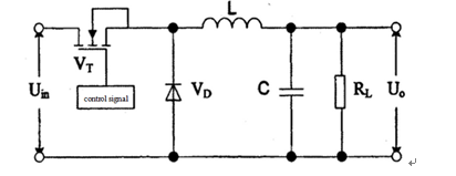
Fig. 1. The main circuit of buck DC-DC converter
According to design of TL494 (single ended buck DC-DC converter) and using continuous current mode, when the switching power supply works on CCM, the turn-on time is DT and Ii uplift amount is [(Uin-Uo) *DT]/L in a period; the turn-off time is (1-D)T and Ii uplift amount is [(Uin-Uo) *DT]/L. In the steady state, the two working principles from the top surface of the non-isolated circuit can make ILequal at the end and begining of each cycle. So the following expression can be obtained.
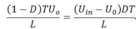
Sothe relationship of duty ratio D, Uin and Uo is as follows:

Fig. 2 is the main waveform of CMM buck type switching power supply.In every period, the charge transferred by ILis the same with the charge got by Io at the same time.
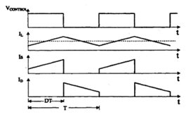
Fig.2. TheCMM waveform of continuous current mode
If you want to know more, please feel free to contact us.
Our web site is
http://www.analogtechnologies.com/