NTC thermistors are used for temperature measurement and control, temperature compensation, surge-current suppression, and environmental sensing. The previous note listed short circuit, open circuit, and resistance offset as the common failures. Those symptoms are correct, but the useful question is
why they happen and how to prevent them. The core idea: a thermistor outputs
resistance, not temperature — treat it as a system, not a magic bead.
Download the full white paper (PDF)
9 pages · formulas, glass/epoxy guidance, failure table, and a release checklist
Download PDF ↓
1. A thermistor outputs resistance, not temperature
An NTC thermistor is a thermally sensitive semiconductor resistor: its resistance falls as temperature rises (the opposite of a metal resistor). The part reports resistance; the circuit must translate it into temperature.
R(T) = R25 × exp[ B × (1/T − 1/298.15) ]
T in kelvin · cold → high R · hot → low R
Beta (B) is derived from two temperature points and is handy for selection; Steinhart–Hart modeling uses three points and is more accurate across a wide range. Always confirm R25, beta, tolerance, power, and temperature limits against the datasheet of the exact part.
|
Design term |
Plain meaning |
Why it matters |
|
R25 |
Resistance at 25 °C |
Sets the nominal value read by a divider or controller. |
|
Beta (B) |
Curve steepness |
Higher beta = stronger change per °C, over a narrower range. |
|
Tolerance |
Part-to-part spread |
Determines whether calibration is needed. |
|
Dissipation factor |
Power for 1 °C self-heating |
Controls self-heating error. |
|
Max power / current |
Safe electrical boundary |
Prevents thermal runaway, melting, or open/short failure. |
|
Body material |
Glass or epoxy shell |
Sets temperature range, sealing, drift, cost, and mechanics. |
2. Glass vs. epoxy bodies
|
Body |
Strengths |
Watch-outs |
|
Epoxy-coated |
Low cost, small, fast; good for moderate environments and leaded assemblies. |
Check max temperature, moisture, chemicals, drift, potting compatibility. |
|
Glass-encapsulated |
Hermetic seal, high stability, high-temperature and harsh-environment capability; precision. |
Rigid body still needs protection from point impact, lead stress, mounting strain. |
3. Why failures happen: not magic, just physics
Most failures trace to electrical overheating, mechanical stress, process abuse, or environmental attack. In a properly biased 10 kΩ-class divider the current is tiny, so everyday field concerns are cracking, drift, moisture ingress, solder stress, and rework damage. Burnout becomes realistic only when the part is shorted to a rail, forced to dissipate too much power, or misused as an inrush-current limiter.
Thermal runaway is the most dangerous loop: current makes power (P = I²R), power heats the part, heat lowers NTC resistance, lower resistance lets more current through. Without a series resistor, current limit, or adequate power rating, the part can burn, crack, short, or open.
|
Symptom |
Likely cause |
Practical prevention |
|
Open circuit |
Surge energy, cracked body, broken lead |
Limit energy; support cables; avoid lead bending at the bead; respect process limits. |
|
Short / very low R |
Severe overheating or material damage |
Add series resistance / current limit; observe max power and permissible current. |
|
Wrong-but-plausible drift |
Rework heat, aging, moisture, chemical ingress |
Right body; control rework; calibrate or sanity-check where accuracy matters. |
|
Intermittent reading |
Board flex, cracked solder joint, lead fatigue |
Correct land pattern, strain relief, smart board placement. |
|
Slow response |
Wrong package or poor thermal coupling |
Thin adhesive, close mounting, a good thermal path. |
The quiet killer: a believable but wrong resistance can mislead a battery, TEC, laser, medical, or industrial control loop while every reading still looks fine. Open and short are loud; drift is the lie the controller trusts.
4. Sensing NTC is not an inrush-current limiter
One of the most common design mistakes. Both are NTC devices, but their missions are opposite — like a doctor reading a thermometer (low current) versus heating it with a lighter first.
|
Feature |
Sensing NTC |
Inrush-current NTC |
|
Main job |
Measure / compensate temperature |
Limit turn-on surge current |
|
Self-heating |
As low as practical |
Intentional and large |
|
Typical circuit |
Voltage divider into ADC / controller |
Series element in the power input |
|
Failure if misused |
Bad readings, drift, burnout |
Overheating, high steady loss, fails to reset |
5. Reading an NTC cleanly
For most controllers the thermistor sits in a voltage divider into an ADC. If the divider source equals the ADC reference, the reading is ratiometric and less sensitive to reference variation. Don't default the fixed resistor to R25 — size it for the actual hot-to-cold span:
Rfixed ≈ √( Rhot × Rcold )
geometric mean of the endpoint resistances → best usable ADC range over the band
6. Thermal Ohm's law: the hidden circuit
Thermal design mirrors V = I·R: temperature rise acts like voltage, heat flow like current, thermal resistance like electrical resistance.
ΔT = Q × Rθ
the bead reads its own body temperature, not the target's
A thermistor on a laser diode, battery cell, heat sink, TEC cold plate, or motor winding reads truth only if the thermal path is good and self-heating is small. Thick adhesive, air gaps, long leads, and poor clamping add thermal resistance, so the sensor is delayed and biased. Make it small, mount it close with a thin conductive bond, strain-relieve the leads, and keep measurement power low.
7. Mounting: many electrical failures start as mechanical abuse
• Use datasheet land patterns and control solder volume — too much adds stress, too little risks dropout.
• Avoid post-mount board bending near split lines, screws, and impact points; chip cracks start there.
• For leaded bead parts, never use the bead as a handle — bend leads with tooling away from the bead.
• Add strain relief; don't let potting or adhesive become a rigid lever that feeds cable motion into the bead.
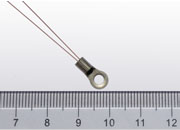
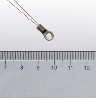 Physical photo of an NTC thermistor with ring lug
Use this paper as a design-review and failure-analysis guide
Full physics, formulas, glass/epoxy guidance, and the complete release checklist are in the PDF
Download full PDF ↓