The forward voltage (Vf) of an LED is the minimum anode-to-cathode voltage needed before significant current flows and light is emitted. It is not a fixed number: it is set by the semiconductor bandgap and varies by color, temperature, current, and manufacturing bin. Red/yellow LEDs (AlGaInP) turn on near 1.8–2.2 V, while green/blue/white LEDs (InGaN/GaN) need about 3.0–3.5 V — a difference that directly drives supply selection, series-string topology, and driver headroom.
Download the full white paper (PDF)
AWPLED-04 · 11 pages · bandgap physics, I-V data, worked examples, driver selection, and a design checklist
Download PDF ↓
1. Why forward voltage varies by color
When an electron recombines across the junction it releases the bandgap energy as a photon, so the same material property sets both the emission wavelength and the minimum forward voltage. The practical relation is:
Vf,min (V) ≈ 1240 / λ (nm)
shorter wavelength → wider bandgap → higher forward voltage
A red LED (λ ≈ 630 nm) needs about 1.97 V; a blue LED (λ ≈ 470 nm) about 2.64 V. Real operating Vf runs 5–20% above this minimum because of series and contact resistance and the carrier injection needed for useful light.
| Color |
Material |
Wavelength (nm) |
Typical Vf |
Vf range |
Temp. coeff. |
| Red | AlGaInP | 620–645 | 2.0 V | 1.8–2.2 V | −2.0 mV/°C |
| Orange | AlGaInP | 590–620 | 2.1 V | 2.0–2.2 V | −2.0 mV/°C |
| Yellow | AlGaInP | 570–590 | 2.1 V | 1.8–2.4 V | −2.0 mV/°C |
| Green | InGaN | 520–535 | 3.0 V | 2.9–3.5 V | −3.0 mV/°C |
| Blue | InGaN | 460–480 | 3.2 V | 3.0–3.5 V | −3.0 mV/°C |
| White | InGaN + phosphor | broad | 3.2 V | 3.0–3.5 V | −3.0 mV/°C |
White LEDs are a blue InGaN die with a yellow phosphor, so electrically they behave like blue LEDs.
2. Supply headroom and series strings
Size the supply for the maximum Vf (LEDs are highest when cold), plus driver dropout:
Vsupply,min = N × Vf,max + Vdropout
e.g. six white LEDs: 6 × 3.3 V + 2 V ≈ 21.8 V → use a 24 V supply for margin
3. Ballast resistor vs. constant-current driver
Worked example — six white LEDs from 24 V at 20 mA. A 300 Ω ballast (R = (24 − 18) / 0.020) works at nominal, but if the supply rises 5% the current jumps to ~23.3 mA (17% over); add a Vf drop from heating and the LED can see ~25% overcurrent, accelerating aging. A constant-current driver instead holds 20.00 mA ±0.1% regardless of supply, temperature, aging, or binning, and recycles excess voltage as efficiency (>90%) rather than burning it as heat.
| Parameter |
Ballast resistor |
Constant-current driver |
| Current accuracy | ±10–25% (varies with Vsupply, T, aging) | <0.1% absolute |
| Noise | Follows supply directly | 300 nA–12 µA P-P (model dependent) |
| Efficiency | 50–80% (headroom dependent) | 85–95% (switching) |
| Protection (OTP/OCP/UVP) | None | Built-in shutdown and hard current limit |
| Current monitoring | None | Real-time output for system feedback |
| Best suited for | Indicators, toys, non-critical lighting | Instrumentation, medical, optical, industrial |
A resistor is fine for non-critical indicators where ±20% current is tolerable. For stable optical output, long lifetime, or noise immunity, a
constant-current driver is the engineering-correct choice.
Thermal runaway (resistor circuits only): temperature rises → Vf drops (ΔVf = TCV × ΔT) → current rises → power and junction temperature rise → loop repeats. A constant-current driver breaks the loop at the current step; OTP adds a second safety net.
4. ATI laser drivers for LED applications
ATI laser drivers were built for laser diodes — even more current-sensitive than LEDs — so they exceed precision-LED requirements: ultra-low noise, <0.1% accuracy, and protection (soft-start, OTP, OCP, UVP, loop-good and current-monitor outputs).
| Application |
LED current |
Recommended driver |
Key advantage |
| Precision indicator / sensor | 0.1–0.5 A | ATLSXA106 (Linear) | Ultra-low noise, 1.5 µA P-P |
| Optical instrumentation | 0.1–1 A | ATLSXA103 (Linear) | 1.2 MHz bandwidth, eval board |
| High-power LED array | 1–6 A | ATLSXA201 (PWM) | High efficiency, 6 A max |
| Industrial illumination | 4–12 A | ATLSXA216 (PWM) | 12 A output, 5.5–15 V input |
| Ultra-low-noise optical | 0.1–1 A | ATLSXA116 (Linear) | 300 nA P-P, best-in-class |
5. Thermal management and design checklist
LED lifetime is exponentially sensitive to junction temperature — roughly halving for every 10 °C rise. For high-power systems, pair the driver with
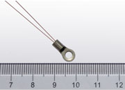
ATI NTC thermistors (junction monitoring),
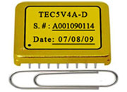
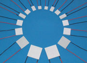
TEC modules (active cooling), and
TEC controllers (closed-loop regulation).
• Use maximum Vf at the lowest operating temperature for the string total (Vf is highest when cold).
• Verify the supply exceeds N × Vf,max + dropout under worst-case line and load.
• Choose driver type: linear for lowest noise, PWM for highest efficiency and current.
• Derate current with temperature (about 2.5% per 10 °C above 25 °C).
• Add monitoring: current-monitor output for feedback, loop-good for open-load fault detection.
• Prototype with ATI evaluation boards before committing to a production layout.
FAQ
What is the forward voltage of a red LED? About 1.8–2.2 V at 20 mA and 25 °C (AlGaInP), depending on wavelength, binning, and current.
Why do blue and green LEDs need more voltage than red? They use wider-bandgap InGaN (2.7–3.4 eV) versus AlGaInP (1.8–2.2 eV); higher bandgap energy needs more voltage to inject carriers.
Can a laser driver drive LEDs? Yes — ATI laser drivers are designed for the more demanding laser-diode case, so their low noise, tight regulation, and protection make them ideal for high-end LED systems.
How many LEDs can I put in series? Nmax = (Vsupply − Vheadroom) / Vf,max. With 24 V, 2 V headroom, 3.3 V white LEDs: about 6.
Get the full white paper and driver selection guide
Bandgap physics, measured I-V curves, full comparison and troubleshooting tables, and the 10-point checklist are in the PDF
Download full PDF ↓