A
thermoelectric cooler (TEC, or Peltier module) spends electrical current to
move heat across a semiconductor junction (the Peltier effect) for controlled cooling or heating. A
thermoelectric generator (TEG) is the reciprocal device: it spends a
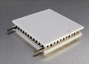
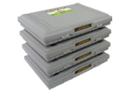
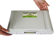
temperature difference to produce DC power (the Seebeck effect). They look almost identical — flat ceramic plates with two lead wires — but are optimized for opposite directions of energy flow.
One buys temperature control with watts; the other sells a temperature difference for watts.
Download the full white paper (PDF)
AWTMTG-05 · Rev. H · 25 pages · theory, governing equations, closed-loop control, the three-gate selection method, reliability, and FAQ
Download PDF ↓
1. TEC vs. TEG: the core difference
Both rely on the same Peltier and Seebeck effects in bismuth-telluride couples; geometry and fill factor are tuned for either cooling COP or generation efficiency. A module optimized for cooling is not optimized for generation — for production designs, use a TEC for control and a TEG for power; don't substitute one for the other.
| Attribute |
TEC (Peltier cooler) |
TEG (Seebeck generator) |
| Energy direction | Electricity → heat movement | Heat → electricity |
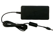
| Driving input | DC current from a TEC controller | Temperature difference across faces |
| Useful output | Cooling (and heating) of a controlled surface | DC electrical power into a load |
| Governing effect | Peltier | Seebeck |
| Key spec | Qcmax, ΔTmax, Imax, Vmax, COP | Power at rated ΔT, matched-load R, open-circuit V |
| ATI product path | TEC modules + TEC controllers | TEG modules |
2. The physics: four effects and the figure of merit
Two effects are useful and reversible (Peltier, Seebeck); two are parasitic (Joule heating, Fourier back-conduction). Good design maximizes the first pair and minimizes the second.
| Effect |
Role |
| Peltier | Pumps heat from the cold face to the hot face — the TEC cooling mechanism. |
| Seebeck | A ΔT produces a voltage — the TEG generating mechanism (and thermocouple feedback). |
| Joule | I²R loss heat; about half returns to the cold side, limiting net cooling. |
| Fourier | Heat conducts back hot→cold down the gradient; sets the maximum achievable ΔT. |
Material quality is captured by the dimensionless figure of merit; commercial bismuth-telluride reaches ZT ≈ 0.8–1.1 near room temperature, which bounds both TEC ΔTmax and TEG efficiency:
ZT = (S² · σ / k) · T
high Seebeck coefficient, high electrical conductivity, low thermal conductivity
3. Governing equations — and the rule that decides success
Cold-side cooling is Peltier pumping minus half the Joule heat minus Fourier back-conduction; the supply provides the pumped heat plus the Joule loss; the hot side must reject the sum of both:
Qc = S·I·Tc − ½·I²·R − K·ΔT
Pin = S·I·ΔT + I²·R
COP = Qc / Pin
Qh = Qc + Pin
the hot side must reject the cooling load plus the electrical input power
Why hot-side removal is non-negotiable: a TEC pumping 20 W of cooling while drawing 30 W must reject 50 W at the hot face. If the sink can't remove it, the hot side heats up, ΔT rises, and cooling collapses — size the heat sink for Qh, not Qc. ATI controllers also limit drive current to ~70% of Imax, where added Joule heat starts to overwhelm added Peltier pumping; keep ΔT under ~30 °C for good COP.
Run in reverse, an open-circuit ΔT produces a Seebeck voltage; under a matched load the TEG delivers maximum power. Because voltage rises with ΔT but matched-load power rises with ΔT², protecting the gradient (flat, well-clamped contacts; a strong cold sink) is the single most important TEG design move:
Voc = S·ΔT · Pload,max = (S·ΔT)² / (4R) at Rload = Rmodule
halving the true ΔT cuts available power roughly fourfold
4. Closed-loop TEC control
A bare DC supply cools one way and cannot warm an object back up when the ambient drops. Precise control needs a closed loop: a sensor at the object, a PID (or Auto-PID) error stage, and a bipolar four-quadrant output that sources current in either polarity to cool or heat — with programmable I/V limits to protect the module.
•
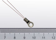
Sensor: a precision
NTC thermistor (or RTD/IC) bonded at the object — a sensor on the heat sink reads stable while the submount drifts.
•
Bipolar drive holds a setpoint against ambient swings in both directions — essential for laser-wavelength stability.
•
Linear vs. PWM: linear output = lowest noise (noise-sensitive lasers/sensors); PWM = highest efficiency at high power.
•
Auto-PID removes manual loop tuning; fully shielded, zero-EMI construction keeps switching noise out of the signal path.
5. The three-gate selection method
Every TEC design must pass three gates
in order. Most engineers guard only Gate 1 (capacity); Gates 2 and 3 are where Regular Temperature modules silently fail in the field.
Gate 1 — Thermal capacity: can it pump Qc at the real ΔT? (Select from the Qc–ΔT curves, not Qmax at ΔT = 0.)
Gate 2 — Temperature class: can the solder/package survive the hot-side or surface temperature?
Gate 3 — Cycling lifetime: can it survive the number of full-current reversals over product life?
A Regular Temperature module carries a max surface temperature around 125 °C; in a hot bay or sealed enclosure that limit — not the electrical design — becomes the binding constraint. ATI
High-Temperature −H TECs use ~238 °C internal solder and run to 200 °C. The dominant wear-out mechanism is thermal-cycling fatigue, tracked as a rise in AC resistance (ACR); ATI defines a 10% ACR rise as end of life:
| TEC class |
Reversals to 10% ACR rise |
Best fit |
| Regular Temperature | ≈ 500–1,000 | Steady-state cooling, infrequent polarity changes |
| Long-life (ATE1-TC) | up to 20,000 | PCR/qPCR blocks, repeated heat/cool cycling |
| Long-life high-COP (ATE1-TCHE) | up to 20,000 | High-cycling duty where COP also matters |
For any design that reverses current frequently, the long-life family is not a premium upgrade — it is the correct part (about 20× the endurance).
6. Reliability and failure modes
| Challenge |
Root cause |
Response |
| Hot-side runaway | Sink can't reject Qh; Th rises, Qc falls | Size sink for Qc + Pin with margin; improve airflow; use −H if surface is hot. |
| ACR rise / short life | Micro-cracks from cycling, overcurrent, shock | Use long-life ATE1-TC/TCHE; pre-screen ACR; avoid shock. |
| Shear-cracked ceramic | Lateral loads on brittle ceramic | Even, controlled compression; flat lapped surfaces. |
| Condensation / ice | Cold surface below dew point | Seal, insulate, purge, or raise setpoint / add interlock. |
| Loop oscillation | Sensor lag or compensation mismatch | Place sensor at the object; use PID/Auto-PID. |
Measure ACR, not DC resistance. AC resistance reveals the micro-cracking a multimeter's DC reading hides — use an LCR meter, pre-screen at incoming inspection, and trend it in service to catch a fatiguing module before it fails.
7. ATI product selection
| Need |
ATI family |
Notes |
| Precision cooling/heating | TEC modules (rect./circular) | Match Qcmax, ΔTmax, Imax, Vmax; 7–288 couples; circular for optical paths. |
| Hot environment | High-Temperature −H TEC | ~238 °C solder; operation to 200 °C. |
| Frequent current reversal | Long-life ATE1-TC / ATE1-TCHE | Up to 20,000 reversals to 10% ACR; TCHE adds higher COP. |
| Regulate temperature | TEC / Peltier controllers | Bipolar, I/V-limited, PID/Auto-PID, linear or PWM, zero EMI. |
| Generate power from heat | TEG modules | Spec power at the real loaded ΔT; match load to module R. |
| Sense temperature | Thermistors | Glass NTC, ~±0.05 °C; ~0.8 mm bead for laser submounts. |
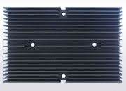
| Reject hot-side heat | Heat sinks | Size Rθ for Qh = Qc + Pin. |
FAQ
TEC vs TEG — what is the difference? A TEC uses electricity to move heat and control temperature; a TEG uses a temperature difference to produce electricity. Same construction, opposite directions.
Is a Peltier cooler the same as a TEC? Yes — "
Peltier module," "Peltier cooler," and "TEC" all name the same solid-state heat pump that cools or heats with DC current.
Can a TEC heat as well as cool? Yes. Reversing current reverses heat flow, which is why bipolar controllers hold a setpoint against ambient swings in both directions.
Which TEC fits PCR / frequent reversal? A long-life ATE1-TC or ATE1-TCHE rated to ~20,000 reversals — vs. ~500–1,000 for Regular Temperature, which may pass early tests but fatigue within weeks.
Why doesn't my TEC reach the target temperature? Almost always inadequate hot-side heat removal. Improve the heat sink first (size for Qh = Qc + Pin); if the surface temperature is the limit, move to a −H module.
How efficient is a TEG? Typically a few percent up to ~8%, bounded by ZT and the available ΔT — best for harvesting waste heat, not primary generation.
Get the full reference and selection guide
Full derivations, cartoons, a worked sizing example, the three-gate decision tree, troubleshooting, 20-item FAQ, and a one-page quick-reference card are in the PDF
Download full PDF ↓