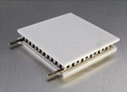
Designing a heat sink for a thermoelectric (TEC / Peltier) cooler is not the same as heat-sinking a CPU, MOSFET, or LED. A TEC does not destroy heat — it moves heat from the cold side to the hot side. So the heat sink at the hot side must reject the sum Q_hot = Q_c + P_electrical, which for typical operating points is two to five times the cold-side load. Get the sink wrong and a TEC system doesn't gently warm up like a CPU — it saturates: as T_hot climbs, the TEC's cooling capacity falls, the controller demands more current, P_electrical rises, T_hot rises further, and the loop misses setpoint at worst-case conditions.
The whole problem reduces to two relations. The hot-side load the sink must reject:
Q_hot = Q_c + P_electrical (P_electrical = V_TEC · I_TEC)
and the heat-sink sizing inequality — the most-cited equation in the guide:
R_θSA ≤ (T_hot,max − T_ambient,max) / Q_hot − R_TIM
Heat flow is the thermal analog of current, ΔT the analog of voltage, and R_θ the analog of resistance (ΔT = Q · R_θ). The hot-side stack is just three resistances in series — TIM joint, heat-sink base spreading, and fin-to-air convection — and the convection term usually dominates.
• Use operating-point T_hot,max, not the absolute maximum. Read T_hot,max from the TEC performance curves at your actual operating point — not the datasheet header rating. The two can differ by 20–40 °C; using the wrong one is the most common serious sizing error.
• Apply margin to R_θSA, not to power. A 2× margin means half the thermal resistance (twice the cooling capacity), not twice the power.
• Use fan operating airflow, not free-flow CFM. A heat sink presents static pressure; the real operating point is where the fan curve meets the system-resistance curve — typically 30–60% of free-flow CFM.
• Size sub-ambient designs for the worst case. Below ambient, the TEC also pumps a parasitic heat leak, so Q_hot is much higher than a room-temperature estimate and you must insulate aggressively.
• Size for peak transient Q_hot. Ramping loads (PCR blocks, laser pull-down) demand peak Q_hot during the ramp, well above the steady-state average.
(1) Derive Q_hot from the TEC operating point (worst-case ambient, peak load, deepest ΔT). (2) Define the worst-case ambient at the fins — enclosures often run 10–15 °C above room. (3) Establish T_hot,max from the TEC curves at your operating point. (4) Calculate required R_θSA, subtract R_TIM, then apply environment margin. (5) Select heat-sink type and cooling mode. (6) Validate the assembled stack at worst-case conditions, holding for at least 5τ before reading steady-state temperatures.
| Operating environment | Margin on R_θSA | Why |
|---|---|---|
| Controlled lab / production floor | 1.5×–2× | Stable ambient, clean air, controlled airflow |
| General OEM (instrument enclosure) | 2×–3× | Enclosure restriction, dust, ambient excursions |
| Outdoor / kiosk / harsh | 3×–5× | Solar gain, dust loading, fan aging, wide swings |
| Type | Typical Q_hot | Best fit |
|---|---|---|
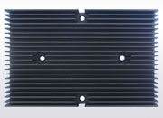
| Extruded aluminum | 5–50 W | General OEM, lab/instrument, photonics enclosures |
| Bonded-fin / skived Al or Cu | 20–200 W | Telecom, high-power photonics, dense racks |
| Vapor chamber + fins | 30–300 W | High heat-flux loads, hotspot spreading |
| Heat pipes (remote rejection) | 50–500 W | Tight space at TEC, larger sink elsewhere |
| Liquid cold plate + exchanger | 50 W – multi-kW | High-power lasers, sealed/sub-ambient designs |
Roughly: passive natural convection suits ≤10–30 W and acoustic/vibration-sensitive instruments; forced air covers ~10–100 W; liquid earns its complexity above ~50 W or where fans are excluded. Doubling airflow cuts R_θSA by 30–40%; cutting R_θSA in half needs roughly 5× the envelope volume.
Even polished surfaces touch only at microscopic peaks; trapped air (~0.024 W/m·K) dominates contact resistance until a thin TIM displaces it. Keep the TEC ceramic and sink base flat to ±0.025 mm, apply ~1.0–2.0 MPa uniform compression, and use the thinnest uniform TIM bond line that fills the roughness — overspreading grease raises resistance, not lowers it. R_TIM of 0.1–0.2 K/W is often half a good R_θSA, so never leave it out of the budget.
Why can't I use the TEC's maximum T_hot rating to size the sink? Because at the absolute maximum the TEC may no longer pump the required Q_c at the required ΔT. Use the operating-point T_hot,max from the performance curves — it can be 20–40 °C lower.
How much margin should I add to R_θSA? 1.5–2× for controlled labs, 2–3× for general OEM, 3–5× for outdoor/harsh. Margin goes on resistance, not power.
Can one heat sink serve multiple TECs? Yes if they are co-located and run together — but sum their Q_hot for sizing. For high power or precision setpoints, separate sinks reduce cross-coupling.
Does anodizing help? For natural convection, modestly (radiation, ε≈0.85 vs 0.05 bare). For forced air it's usually small because convection dominates — but anodize anyway for corrosion/cosmetics.
What's the most common serious mistake? Using the absolute-maximum T_hot instead of the operating-point T_hot,max. It is the single most frequent heat-sink-sizing error in TEC systems.
Companion white papers: AWP-TECM-01 (TEC module fundamentals) · AWP-TECC-02 (TEC controller selection) · AWP-TECC-03 (full TEC cooling-system design). Related: TEC Modules · TEC Controllers · Precision Thermistors · Laser Drivers · All White Papers · Contact