White Paper AWP-TECC-03 · Rev 2.9 · June 2026 · Analog Technologies, Inc.
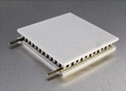
Designing a TEC cooling system is a six-step process: characterize the cold-side thermal load, define the worst-case ambient envelope, select a TEC module from its datasheet performance curves at the actual operating point, size the heat sink for the resulting hot-side heat, choose the sensor placement and mounting, and validate the assembled stack against a worst-case test envelope before production. The TEC controller is selected separately per companion paper AWP-TECC-02.
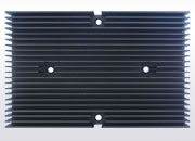
Four components must be sized together against the application's thermal load, ambient envelope, and target setpoint: the TEC module (heat-pumping capacity at worst-case ΔT), the heat sink (Q_hot rejection at worst-case ambient), the temperature sensor (placement that determines what the loop can resolve), and the mechanical stack (TIM, compression, orientation, sealing).
Q_hot = Q_c + P_electrical ·
P_electrical = V_TEC × I_TECΔT_TEC = T_hot − T_cold,setpoint ·
R_θSA ≤ (T_hot,max − T_ambient,max) / Q_hot
| Application | Cold-side load | ΔT | TEC module direction | Heat-sink direction |
|---|---|---|---|---|
| Miniaturized photonic sensor (Raman, gas analyzer) | ≤ 1 W | ≤ 20 °C | Compact single-stage | Passive or small forced-air |
| Laser-diode wavelength stabilization | 0.5–5 W | 15–35 °C | Single-stage matched to package | Forced-air, controlled airflow |
| Mid-power precision (OCXO, photodetector, ADC) | 1–10 W | 15–40 °C | Single-stage, COP-oversized | Forced-air with margin |
| PCR / instrumentation thermal block | 10–30 W | 40–90 °C | Cycle-life-rated single-stage | Forced-air, cycle margin |
| Outdoor kiosk / enclosure cooling | 20–60 W | Window-mode | Enclosure-class single-stage | Forced-air, dust margin |
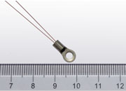
Q_load = Q_active + Q_passive at worst-case operating point. Active loads include laser diodes, GPUs, photodetectors. Passive loads are heat flowing into the cold object via convection, conduction, and radiation.R_θSA ≤ (T_hot,max − T_ambient,max) / Q_hot. Apply 1.5–2× margin for lab/production, 2–3× for industrial OEM, 3–5× for outdoor or dusty environments.Controller datasheet stability is measured at the sensor under defined laboratory conditions. Stability at the controlled object depends on the full thermal stack. For sub-10 mK (<0.01 °C)-class targets:
A poorly assembled stack can lose 20–40% of cooling capacity to parasitic resistance at TIM interfaces. Apply thin uniform TIM (target 25–100 µm) on both ceramic faces. Lap mating surfaces flat to ±0.025 mm (TIR ≤ 0.076 mm). Use four screws with spring washers for uniform compression (typical target 1.0–2.0 MPa over ceramic-face area — verify against the specific module's datasheet).
| TIM thickness | R_TIM per interface | Temperature penalty at 12 W |
|---|---|---|
| 50 µm (ideal) | 0.05 °C/W | 0.6 °C |
| 100 µm (acceptable) | 0.10 °C/W | 1.2 °C |
| 200 µm (too much) | 0.20 °C/W | 2.4 °C |
| 500 µm (excessive) | 0.50 °C/W | 6.0 °C |
| If You Need… | Load Range | Family Group | Example Part Number |
|---|---|---|---|
| Smallest footprint | ≤ 1 W | TEC14M (14 × 14 mm SMT) | TEC14M5V3R5AS |
| General OEM prototyping | 1–3 W | TECA1 (DIP) | TECA1-5V-5V-DAH |
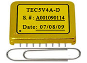
| Lower-mid-power 5 V | 2–4 W | TEC5V (hybrid, 4 A) | TEC5V4A-DAH (or -LD) |
| Mid-power 5 V | 4–10 W | TEC5V (hybrid, 6 A) | TEC5V6A-DAH (or -LD) |
| High current / high ΔT | 10–50 W | High-current series | TEC18V15A, TEC24V10A, TEC24V15A |
| Autonomous enclosure cooling | 20–60 W | ATFC (window mode + fan PWM) | ATFC106D (12 V) |
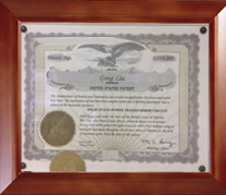
ATI's hybrid topology (U.S. Patent 6,486,643 B2) delivers high efficiency together with low output ripple in a single module — substantially reducing the external LC filtering that pure-PWM controllers require, while avoiding the controller self-heating penalty of pure-linear designs. ATI supplies matched TEC controllers, TEC modules, precision thermistors, and evaluation boards from a single source, simplifying compatibility checks across the controller-sensor-TEC operating envelope. US-based applications engineering reviews qualified OEM project specifications and recommends a starting controller family, precision grade, and evaluation board.
Order at shop.analogtechnologies.com. For applications outside these envelopes, contact ATI applications engineering.
Email: sales@analogti.com ·
Phone: 408-748-9100 ·
Web: www.analogtechnologies.com ·
Shop: shop.analogtechnologies.com
Analog Technologies, Inc., San Jose, California, U.S.A.
© 1997–2026 Analog Technologies, Inc. All rights reserved.