White Paper AWP-TECC-02 · Rev 2.8 · June 2026 · Analog Technologies, Inc.
A TEC controller is a closed-loop thermal servo: it reads a temperature sensor (typically an NTC thermistor), compares the measurement against a programmable setpoint, computes a PID correction, and drives regulated bidirectional current into a thermoelectric (Peltier) cooler to hold the load at the target temperature.
Short answer: Match a TEC controller to the TEC module's actual operating-point current and voltage (read from the TEC datasheet performance curves at your worst-case Q_c, ΔT, and hot-side temperature) with appropriate current and voltage headroom, pick the precision grade that meets the application's stability target, and validate the choice on the matched evaluation board before committing to PCB layout.
| Application Q_load | Typical ΔT | PCB Constraint | Starting Family |
|---|---|---|---|
| ≤ 1 W | ≤ 60 °C | Severely constrained, SMT | TEC14M |
| 1–4 W | ≤ 50 °C | Moderate, DIP acceptable | TECA1 or TEC5V4A |
| 4–10 W | ≤ 40 °C | Moderate, DIP acceptable | TEC5V6A |
| 10–50 W | ≤ 30 °C | Relaxed | TEC18V15A, TEC24V10A, or TEC24V15A |
| 10–60 W (enclosure) | any | Enclosure cooling with fans | ATFC106D |
First-pass screening only — final controller selection must be based on I_TEC and V_TEC from the TEC datasheet performance curves, not on Q_load alone.
The power output stage of a TEC controller can be built three ways, each with a characteristic efficiency, ripple, EMI, and BOM-cost signature. For most precision OEM applications — laser-diode cooling, photonics, medical instruments — a hybrid topology that combines a switch-mode stage with a linear post-regulation stage delivers the best balance: high efficiency, low output ripple, and low EMI in a single module.
| Metric | Pure Linear | Pure PWM | ATI hybrid topology |
|---|---|---|---|
| Efficiency (typical) | 20–40% | 85–93% | >90% at standard test point |
| Output ripple | <0.05% | 1–5% (typically requires output filtering) | Low without external filter |
| Switching EMI | None | Radiated + conducted | Linear post-regulator attenuates switching ripple at TEC output |
| Controller self-heating | Significant | Low | Moderate |
| Best fit | Linear-only benchtop, ultra-low-EMI | High-power, EMI-tolerant | Common starting point for precision OEM designs |
Datasheets often conflate three different parameters: Stability is the peak-to-peak variation of the regulated temperature at steady state. Accuracy is the offset between the regulated mean and the true thermodynamic temperature of the load. Resolution is the smallest temperature change the controller can detect or command. A controller can be highly stable but inaccurate, or accurate but coarse — these are independent specifications.
| Grade | Setpoint Voltage Accuracy | Setpoint Temp Equivalent | Typical Application |
|---|---|---|---|
| -D | ≤ 5 mV | ≈ 0.05 °C (10 kΩ NTC at 25 °C) | Lab equipment, industrial process control |
| -DA | ≤ 2 mV | ≈ 0.02 °C | Mid-precision OEM, photodetectors |
| -DAH | ≤ 0.5 mV | ≈ 0.005 °C | Laser-diode wavelength lock, OCXO ovens |
| Suffix | Variant Type | Meaning |
|---|---|---|
| -D / -DA / -DAH | Precision grades | Internal compensation, factory-tuned for typical thermal loads. Differ in setpoint voltage accuracy (see grade table above). |
| -NT | User-configurable network | Compensation and/or range network exposed for external configuration. For non-standard thermal loads. Scope varies by family — see datasheet. |
| -LD | Laser-diode configured | Internal compensation and operating envelope configured for laser-diode thermal loads (DFB, VCSEL, Fabry-Pérot, QCL). |
| Family | Input Range | Current | Use When |
|---|---|---|---|
| TEC14M | 5 V | ≤ 3.5 A | 5 V system, small PCB (14 × 14 × 2.2 mm SMT). Miniaturized OEM, handheld photonics. |
| TECA1 xV-xV | 3.3 V or 5 V | ≤ 2.5 A | Battery or 5 V rail, DIP package. Prototyping, low-volume production. |
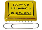
| TEC5V4A / TEC5V6A | 5 V | 4 A / 6 A | 5 V rail, mid-power. Higher-power laser-diode cooling, photonics. DAH grade widely used. |
| TEC18V15A | 6–18 V | ≤ 15 A | Flexible industrial supply, ±15 V output. Auto-PID, programmable protections. |
| TEC24V10A | 5.5–25 V | ≤ 10 A | 24 V industrial / telecom rail. |
| TEC24V15A | 5.5–24 V | ≤ 15 A | Flexible high-current, spans 12 V and 24 V applications. |
| ATFC106D | 12 V | ≤ 20 A | Kiosk / enclosure cooling, window-mode with integrated fan PWM. Not for precision continuous-current loads. |
The high-current series (TEC18V15A, TEC24V10A, TEC24V15A) share footprint, pinout, and a single shared evaluation board (TEC24V15AEV2.2). All ATI continuous-current families use the hybrid topology.
| Application | Recommended Controller | Why |
|---|---|---|
| Laser-diode wavelength stabilization (1–3 W, ~±0.001 °C target) | TECA1-5V-5V-DAH or TEC5V4A-DAH | DAH for telecom-grade precision; hybrid topology for low EMI near wavelength locker. -LD variant available. |
| PCR thermal cycler (10–30 W ramp, 4–95 °C) | TEC18V15A | 15 A capability for ramp; Auto-PID for unit-to-unit variation; low conducted noise back into supply. |
| Outdoor kiosk display cooling (30–60 W, window mode) | ATFC106D | Window-mode setpoint matches the "keep below 40 °C" requirement; integrated fan PWM; 12 V signage rail. |
| Miniaturized photonic sensor (≤ 1 W, 5 V battery) | TEC14M5V3R5AS | 14 × 14 mm SMT footprint fits dense carriers; hybrid for low ripple near TIA / detector front end. |
| LIDAR APD receiver (3–5 W, ±0.01 °C) | TEC5V6A-DAH | 6 A absorbs bursty transient loads during pulse operation; hybrid for low EMI near TIA front end. |
| If You Need… | Load Range | Family Group | Example Part Number |
|---|---|---|---|
| Smallest footprint | ≤ 1 W | TEC14M (14 × 14 mm SMT) | TEC14M5V3R5AS |
| General OEM prototyping | 1–3 W | TECA1 (DIP) | TECA1-5V-5V-DAH |
| Lower-mid-power 5 V | 2–4 W | TEC5V (hybrid, 4 A) | TEC5V4A-DAH (or -LD) |
| Mid-power 5 V | 4–10 W | TEC5V (hybrid, 6 A) | TEC5V6A-DAH (or -LD) |
| High current / high ΔT | 10–50 W | High-current series | TEC18V15A, TEC24V10A, TEC24V15A |
| Autonomous enclosure cooling | 20–60 W | ATFC (window mode + fan PWM) | ATFC106D (12 V) |
ATI's hybrid topology (U.S. Patent 6,486,643 B2) delivers high efficiency together with low output ripple in the same module — substantially reducing the external LC filtering that pure-PWM controllers require, while avoiding the controller-cooling penalty of pure-linear designs. ATI supplies matched TEC controllers, TEC modules, precision thermistors, and evaluation boards from a single source. US-based applications engineering reviews qualified OEM project specifications and recommends a starting controller family, precision grade, and evaluation board. 29-year track record of providing migration paths when products transition reduces requalification risk on multi-year OEM programs.
Order at shop.analogtechnologies.com. For applications outside these envelopes, contact ATI applications engineering.
Email: sales@analogti.com ·
Phone: 408-748-9100 ·
Web: www.analogtechnologies.com ·
Shop: shop.analogtechnologies.com
Analog Technologies, Inc., San Jose, California, U.S.A.
© 1997–2026 Analog Technologies, Inc. All rights reserved.