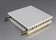
A thermoelectric cooler (TEC), also called a Peltier module, is a solid-state heat pump that moves heat through bismuth-telluride (Bi2Te3) semiconductor couples when DC current is applied. With no compressor, refrigerant, or moving parts, a single TEC module can cool below ambient, heat above ambient, or stabilize at a precise setpoint to within ±0.001 °C.
For balanced precision designs, size the module so Qmax ≈ 4–6× the actual cooling load and operate it at 20–35% of Imax. This is the operating band that maximizes COP, minimizes heat-sink burden, and extends module life beyond 200,000 hours.
This 83-page engineering reference takes you from first principles through advanced design, with rigorous equations, three worked examples, a normalized performance-curve library, and a complete reliability framework. You will learn how to:
Every TEC obeys a single energy-balance equation:
The Peltier term (αTcI) pumps heat from cold to hot via electron transport. The Joule term (½RI²) is unavoidable resistive waste. The Fourier term (KΔT) is back-conduction through the module body. Net cooling is what remains. Because Peltier scales linearly with current and Joule scales with I², an optimum operating current always exists well below Imax.
Every TEC module datasheet specifies Qmax, ΔTmax, Imax, and Vmax at a reference hot-side temperature (typically 27 °C). These four numbers determine all module physics through closed-form bridge equations. For the ATE1-127-8AS: Qmax = 68.9 W, ΔTmax = 66 °C, Imax = 8.0 A, Vmax = 15.4 V.
The heat sink must reject Qh = Qc + Pin — the cooling load plus the electrical input power. For COP = 1, the heat sink sees double the cooling load. Undersized hot sides are the leading cause of TEC field failure.
The Qmax-to-Qc ratio depends on your design priority. Most precision applications belong in the Balanced row.
| Design Target | Qmax/Qc | I/Imax | Typical COP | Best For |
|---|---|---|---|---|
| Minimum size | 1.5–2× | 0.9–1.0 | 0.3–0.8 | TO-can lasers |
| Balanced (default) | 4–6× | 0.20–0.35 | 1.3–2.5 | Precision work |
| Maximum efficiency | 5–8× | 0.15–0.25 | 2.5–4.0 | Battery-powered |
| Maximum ΔT | 10×+ | 0.9–1.0 | 0.1–0.5 | IR detectors |
The paper walks through three complete, internally consistent designs covering the entire TEC operating space:
| Application | Qc / ΔT | Module + Controller | COP |
|---|---|---|---|
| Laser-diode wavelength lock | 9.5 W / 9.6 °C | ATE1-127-5AS + TEC14M5V3R5AS | 3.31 |
| Cooled CMOS imaging sensor | 4.5 W / 44 °C | ATE1-127-8AS + TEC14M12V8AS | 0.17 |
| AI accelerator hotspot cooling | 40 W / −2.3 °C | ATE1-127-15ASH + custom | 14.4 |
The AI hotspot example demonstrates the active heat-spreading regime (negative ΔT), where COP can exceed 10 because the TEC assists natural heat flow rather than fighting it — an emerging architecture for AI accelerator and high-power electronics thermal management.
TECs are the right choice whenever you need precision (better than ±0.1 °C), silence, compactness, sub-ambient operation, or bidirectional control, with a cooling load below ~200 W. Common applications:
Five mistakes account for over 80% of TEC field failures. The white paper covers all ten in detail; here are the most common:
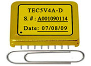
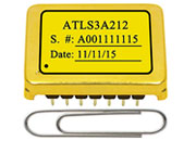
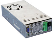
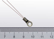
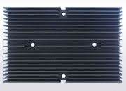
A complete TEC system needs four matched components — module, controller, thermistor, and heat sink. ATI designs and manufactures all four to work together as a single ecosystem:
| Component | Description | Browse |
|---|---|---|
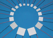
| TEC modules | ATE1-127 series, 49 variants, 20–252 W cooling capacity | TEC Modules → |
| TEC controllers | Linear-drive, ±0.001 °C stability, <0.1% ripple | TEC Controllers → |
| NTC thermistors | 10 kΩ β = 3977 K, ±0.1 °C interchangeable | Thermistors → |
83 pages · all performance curves · three worked examples · complete FAQ · equation cheat sheet
Download PDF (AWP-TECM-01) →White Paper AWP-TECM-01 · Rev. 2.6 · June 2026
Analog Technologies, Inc. · San Jose, California · www.analogtechnologies.com
Sales: sales@analogtechnologies.com · +1 408-748-9100 · Copyright © 1997–2026 ATI. All rights reserved.