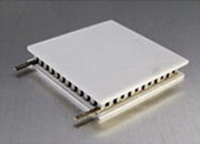
A TEC (thermoelectric cooler) system uses electrical power to actively control temperature. A TEG (thermoelectric generator) system harvests electrical power from an existing temperature difference. The physics are reciprocal — both rely on the Peltier and Seebeck effects in the same solid-state Bi2Te3 materials — but the engineering objectives are opposite.
Optimized TECs and optimized TEGs are not automatically interchangeable. A TEC may generate voltage from a temperature difference, but reuse as a TEG requires verifying solder system, temperature rating, electrical resistance, sealing, and datasheet limits.
| If You Need To… | Choose |
|---|---|
| Hold an object at a controlled temperature, or cool below ambient | TEC — module + controller + temperature sensor |
| Stabilize a laser diode, detector, or precision instrument | TEC — closed-loop temperature control |
| Harvest electrical power from an existing sustained heat flow | TEG — module + DC-DC power-management converter |
| Generate regulated DC from waste heat, exhaust, or solar/process heat | TEG — electrical operating-point management (often MPPT) |
| Reuse a TEC as a TEG (or vice versa) without redesign | Verify first — solder, temperature, resistance, sealing |
Both TECs and TEGs rely on the coupling between heat flow and electrical charge in thermoelectric materials. The same solid-state physics is used in two opposite ways:
These two opposite questions lead to opposite choices for module construction, electronics, mounting, and protection. Reciprocal physics does not mean reciprocal product qualification.
| Aspect | TEC System | TEG System |
|---|---|---|
| Primary mission | Control temperature; move heat on command | Generate power from sustained ΔT |
| Energy direction | Electrical input → heat pumping | Heat flow → electrical output |
| Physical effect | Peltier: current drives heat pumping | Seebeck: ΔT produces voltage |
| System electronics | TEC controller with temperature feedback | DC-DC converter, often with MPPT |
| Design priority | Maximize COP at required cooling load | Maximize safe sustained ΔT within limits |
| Operation priority | Hold TMO at setpoint (closed-loop) | Operate near maximum-power point |
| Thermal focus | Reject Qh = Qc + Pin from hot side | Maintain ΔT; reject Qcold,reject ≈ Qhot − Pelec |
| Key figures of merit | COP, Qc, ΔT, stability, ripple | Voc, internal resistance, matched-load power |
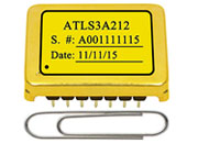
A TEC should normally be driven by a TEC controller, not a raw power supply. The controller reads a temperature sensor on the temperature-managed object (TMO), compares it to the setpoint, and adjusts TEC current through a regulated H-bridge or linear stage. The desired drive is low-ripple regulated DC: the average DC component drives net Peltier heat pumping, while ripple adds I²R Joule heating without control benefit. Raw PWM is not equivalent to a regulated controller — precision applications require low-ripple linear or filtered-switching TEC controllers with current, voltage, and hot-side temperature protection.
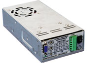
A TEG produces DC voltage and DC current. The first downstream electronics block is normally a DC-DC power-management converter, not an inverter. The converter must accept a variable, source-impedance-limited TEG input and produce a regulated output while managing the TEG's electrical operating point near its maximum-power condition. Low-ΔT harvesting often requires a cold-start mechanism because open-circuit voltage at small temperature differences can fall below the converter's minimum startup voltage. Practical converters implement MPPT (maximum-power-point tracking) or fractional-Voc control rather than a fixed ½·Voc target.
Peltier pumping (linear in I) minus Joule heating (I²) minus Fourier back-conduction. This is why driving a TEC at Imax collapses COP: Joule heating grows faster than Peltier cooling. For balanced precision systems, ATI recommends keeping ΔT below approximately 30 °C wherever the system design allows — a first-pass efficiency guideline, not a hard ceiling.
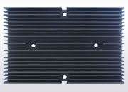
The heat sink must reject Qh = Qc + Pin, not just Qc. Undersized hot-side heat sinking is the most frequent avoidable TEC system mistake.
Maximum power transfer occurs when load resistance equals internal resistance (matched load). Do not design for exactly ½·Voc — this is a first-order sizing starting point, not an operating rule. Use MPPT or fractional-Voc control that adapts to temperature.
A thermoelectric module can sometimes be operated in the opposite mode for demonstration or limited use, but optimized TECs and optimized TEGs are not automatically interchangeable. Before reusing a TEC as a TEG or a TEG as a TEC, verify material grade, solder temperature rating, electrical resistance, mechanical limits, sealing, and expected temperature range.
| Reliability Topic | TEC System | TEG System |
|---|---|---|
| Internal resistance | Rising ACR: element fatigue, microcracks, solder degradation | Solder-joint resistance increase, contact degradation, over-temperature damage |
| Thermal cycling | Current reversals stress pellets, solder joints, interconnects | Less reversal stress, but heat-up/cool-down cycles fatigue joints |
| Hot-side temperature | High Th reduces margin, increases heat-sink burden | Often the critical risk; can soften/melt solder, cause open failure |
| Moisture | Cold-side below dew point corrodes internal joints | Less condensation risk; sealing matters for outdoor/exhaust use |
| Electrical overstress | Ripple or excess current adds I²R heat and fatigue | Overloading/shorting disturbs operating point, adds Joule heat |
Analog Technologies provides TEC modules, TEC controllers, thermistors, and thermal-system components for OEM applications, and offers TEG modules for select applications where applicable. DC-DC converters for TEG power management are typically selected from third-party power-management IC suppliers; final converter selection and validation remain the responsibility of the end-system integrator.
| Product Category | Browse |
|---|---|
| TEC modules (Peltier modules) — Regular Temperature, high-temperature (−H), long-life (ATE1-TC / ATE1-TCHE) | TEC Modules → |
| TEC controllers — low-ripple closed-loop temperature control | TEC Controllers → |
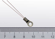
| Thermistors — temperature sensors for TEC control loops | Thermistors → |
| Thermal system components — heat sinks, fans, thermal pads | Thermal Components → |
| TEG modules — thermoelectric generators for waste-heat harvesting (confirm current availability with ATI before design-in) | TEG Modules → |
13 pages · complete comparison tables · design equations · failure mode analysis · application review checklist
Download PDF (AWP-TMTG-01) →For help selecting between TEC and TEG solutions, sizing a TEC controller, or defining TEG converter input requirements, ATI applications engineering can review qualified project inputs and suggest a starting product family or design direction. Send the inputs listed in Section 12 of the white paper and contact ATI:
White Paper AWP-TMTG-01 · Rev. 2.21 · June 2026
Analog Technologies, Inc. · San Jose, California · www.analogtechnologies.com
Sales: sales@analogtechnologies.com · +1 408-748-9100
Copyright © 1997–2026 ATI. All rights reserved. This white paper is an engineering comparison; final component selection should be based on the specific datasheet, operating temperature limits, controller/converter limits, assembly method, and prototype measurements.