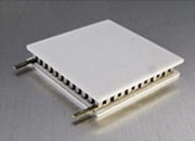
A thermoelectric cooler (TEC) — also called a Peltier module — is a solid-state, bidirectional heat pump based on the Peltier effect. When DC current flows through its bismuth-telluride (Bi₂Te₃) semiconductor couples, heat is pumped from one ceramic face to the other; reverse the current and it switches instantly between cooling below ambient and heating above it. No compressor, no refrigerant, no moving parts, no vibration — just precise, electrically controlled temperature, down to millikelvin stability.
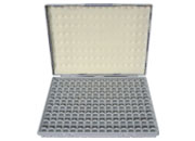
Inside the module, pairs of N-type and P-type Bi₂Te₃ pellets are wired electrically in series and thermally in parallel between two alumina (Al₂O₃) ceramic plates. The net cooling at the cold face is:
Q_c = α·T_c·I − ½·R·I² − K·ΔT
Peltier pumping (α·T_c·I) is linear in current, but Joule self-heating (½·R·I²) grows with the square of current, and Fourier conduction (K·ΔT) constantly leaks heat back through the module. The single most important system equation is that the hot side must reject everything: Q_h = Q_c + P_in. Size your heat sink for Q_h, not just the cooling load.
Every TEC is specified by four parameters. From these you can derive the module's effective Seebeck (α), resistance (R), and conductance (K) for full system math.
| Parameter | Meaning | Condition |
|---|---|---|
| I_max | Max rated current | Produces ΔT_max at Q_c = 0 |
| V_max | Max rated voltage | At I_max, ΔT_max |
| Q_max | Max cooling capacity | At ΔT = 0, I = I_max |
| ΔT_max | Max temperature lift | At Q_c = 0, I = I_max (~65–70 °C single-stage) |
The Goldilocks rule: COP (cooling per watt) peaks near I/I_max ≈ 0.20–0.35, where Peltier pumping still dominates Joule heating. So oversize the module — pick Q_max about 4–6× your real cooling load and operate at 20–35% of I_max. This maximizes efficiency, minimizes hot-side dissipation, and extends module life.
(1) Define cooling load Q_c and required ΔT from your thermal budget. (2) Select a module with Q_max ≥ 4–6× Q_c. (3) Derive α, R, K from the four datasheet values. (4) Find the operating point on the normalized curves. (5) Size the heat sink for Q_h = Q_c + P_in at worst-case ambient. (6) Choose a TEC controller and precision thermistor. (7) Assemble, test, and verify. Standard BiSn-solder modules target a hot side ≤ 50 °C (85 °C absolute max); H-series SnSb modules run to 200 °C for hot under-hood or industrial use.
A working TEC system is more than the module. ATI supplies the whole loop from one vendor:
| Block | Role | ATI product |
|---|---|---|
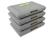
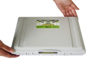
| Heat pump | Moves heat across ΔT | ATE1-127 series TEC modules (20–252 W, V_max 15.4 V) |
| Brain | Closes the loop to ±0.001 °C | Precision TEC controllers |
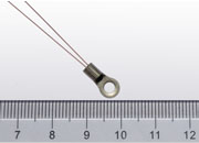
| Sensor | Measures load temperature | Precision thermistors |
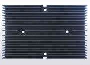
| Hot-side reject | Dissipates Q_h to ambient | Heat sinks |
The ATE1-127 line spans 49 variants and about 63–66 °C of ΔT_max — see the ATE1-127 datasheet for the full table and curves.
Anywhere temperature is a first-order design variable: DFB laser wavelength locking (drift ~0.08 nm/°C), CCD/CMOS sensor cooling (dark current roughly doubles every 6–8 °C), PCR and life-science thermal cycling (±0.5 °C reaction windows), quartz frequency references, IR detectors, and localized hotspot cooling on AI accelerators. The same physics, reversed, also drives thermoelectric generators (TEGs).
• Complete ecosystem — modules, controllers, thermistors, and heat sinks engineered to work together.
• Bidirectional precision — cool, heat, or hold a setpoint to ±0.001 °C with an ATI controller.
• Lead-free, long-life construction — sealed options for moisture environments; H-series for hot-side operation to 200 °C.
• Since-1997 continuity — direct engineering support and same-day shipping from San Jose.
How does a TEC module work? Current through N- and P-type Bi₂Te₃ junctions carries heat from the cold face to the hot face (the Peltier effect). Net cooling is Peltier pumping minus Joule heating and back-conduction: Q_c = α·T_c·I − ½·R·I² − K·ΔT.
What ΔT can a single-stage TEC reach? About 65–70 °C at the hot-side reference with zero load. Under real load the achievable ΔT is lower; cascaded modules can exceed 130 °C.
What size module should I pick? Choose Q_max about 4–6× your real cooling load and run at 20–35% of I_max — that is where COP peaks and lifetime is longest.
What is the difference between a TEC and a TEG? Same materials and physics, opposite direction: a TEC uses current to pump heat; a TEG uses a temperature difference to generate electricity.
Why must the heat sink handle more than the cooling load? Because Q_h = Q_c + P_in — the hot side rejects the pumped heat plus all electrical input power.
Related: TEC Modules · ATE1-127 Datasheet · TEC Controllers · Precision Thermistors · Heat Sinks · TEG Modules · Laser Drivers · White Papers · Contact