A TEC controller is a closed-loop thermal servo that reads a temperature sensor, compares it to a setpoint, computes a PID correction, and delivers regulated bidirectional current to a thermoelectric (Peltier) module — continuously and automatically. Done well, it holds a thermal load to as fine as ±0.001 °C. Unlike an open-loop driver, the controller closes the loop itself: no host firmware required.
A TEC controller is closed-loop and automatic — it measures temperature and drives the TEC to hold a setpoint. A TEC driver is open-loop: it pushes a commanded current with no temperature feedback, so a host MCU must close the loop. A discrete op-amp PID can work but means weeks of analog design, layout, and tuning. If guaranteed stability and fast time-to-market matter, a dedicated TEC controller module removes the riskiest variables.
Setpoint voltage → error amplifier (subtracts sensor feedback) → PID compensation network → patented single-PWM power stage → LC output filter (ripple <1% of I_TEC) → TEC → thermal load. An NTC thermistor, platinum RTD, or IC sensor on the load feeds back to close the loop. Built-in protection adds current limit, voltage clamp, thermal shutdown, and TEMP/I_TEC monitor outputs — no external parts needed.
• Peltier effect: Q_c = α·I·T_c − ½·I²·R − K·ΔT. Joule heating (½I²R) always fights cooling, so the hot side must dissipate Q_h = Q_c + I²R + losses — size the heat sink accordingly.
• Operate at 25–30% of I_max: this is where COP (cooling per watt) peaks, hot-side dissipation is lowest, and TEC lifetime is longest. At 100% of I_max, COP < 1 — emergency cooling only.
• Thermal = electrical analogy: temperature↔voltage, heat flow↔current, τ_th = R_th·C_th. The loop must be tuned to the load's time constant.
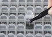
A thermal plant is slow and highly variable (τ from seconds to minutes; ±50% plant variation). Generic "one-size-fits-all" compensation oscillates or responds sluggishly. ATI's analog PID uses five socketed components you select to match your load. Target crossover f_c = 1/(5–10 × τ_th).
| Component | Controls | Effect of increasing |
|---|---|---|
| Rd | Derivative gain | Faster HF response, more noise |
| Cd | Derivative time constant | Extends derivative to lower frequencies |
| Ri | Integral gain | Stronger LF correction, risk of oscillation |
| Ci | Integral time constant | Slower but more stable |
| Rf | Overall loop gain | Tighter control, less stability margin |
Prefer not to tune by hand? Auto-PID models (TEC18V15ADAPID, TEC28V15ASAPID) inject a test signal, identify τ_th and gain, and set optimal compensation in ~60 seconds.
• Patented single-PWM topology (U.S. 6,486,643) — bidirectional current, no shoot-through, >92% typical efficiency, ~25% lower cost and ~35% smaller power stage than multi-switch designs.
• Full six-sided EMI shielding — blocks capacitive, inductive, radiated, and conducted coupling; safe to co-locate millimeters from laser diodes, photodetectors, and precision ADCs.
• User-tunable compensation — five components matched to your thermal load, not a generic average.
• Evaluation boards — validate stability hands-on in minutes instead of weeks of breadboarding.
• Full span, one architecture — 2.7–25 V in, 2.5–15 A out, 14–36 mm; pin-compatible upgrades.
• Since-1997 continuity — no controller model discontinued to date; same-day shipping from San Jose.
| If you need… | Consider | Why |
|---|---|---|
| ±0.001 °C for laser / wavelength lock, ≤6 A | TEC5V6A-DAH | DAH grade, ≤0.5 mV setpoint accuracy |
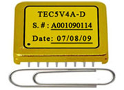
| Most popular laser-cooling module, ≤4 A | TEC5V4A-D/DA/DAH | Compact, grade options for any stability target |
| World's smallest, micro footprint | TEC14M5V3R5AS | 14×14 mm, 3.5 A, 2.7–5.5 V |
| High current up to 15 A | TEC18V15A / TEC28V15A | ±14.5 V / ±20 V output |
| Variable loads or field deployment | TEC18V15ADAPID / TEC28V15ASAPID | Built-in Auto-PID self-tuning |
Grades: D ≤5 mV (±0.05 °C) · DA ≤2 mV (±0.01 °C) · DAH ≤0.5 mV (±0.001 °C achievable). Common applications: DFB/VCSEL & quantum cascade lasers, photodetectors & APDs, optical spectrum analyzers, PCR/medical diagnostics, IR sensors, frequency references, LiDAR, and cooled CCD/CMOS cameras. For APD/PMT bias see high-voltage supplies; for harvesting see TEG modules. See the full TEC controller line.
What's the difference between a TEC controller and a TEC driver? A controller is closed-loop — it reads temperature and adjusts current automatically to hold a setpoint. A driver is open-loop and needs external logic to close the loop.
Can ATI controllers both heat and cool? Yes — all are bidirectional and reverse current direction automatically. Heating-only, cooling-only, and bidirectional are all supported.
What stability can I achieve? ±0.001 °C with DAH-grade controllers under specified conditions: load-matched compensation, a precision thermistor, good thermal isolation, and stable ambient.
When should I use Auto-PID vs. manual tuning? Auto-PID when the load varies between units, the operating range is wide, or tuning time is critical. Manual tuning (with the eval board) when you want the lowest possible noise on a fixed, well-characterized load.
How do I prevent condensation when cooling below dew point? Seal the cold zone with dry gas, use desiccant, and set a minimum-temperature limit in your control logic.
Related: TEC Controllers · TEC Modules · Precision Thermistors · Heat Sinks · Thermal System Components · Laser Drivers · QCL Drivers · TEG Modules · High-Voltage Supplies · White Papers