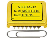
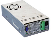
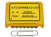
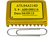
All electrical values taken directly from Table 1 of each part–specific datasheet, TA = 25 °C. Price shown is 1–9 PCs list price; volume tiers (10–49 / 50–249 / 250–499 / ≥ 500 PCs) available via Buy Now.
Engineered Laser-Diode Protection — Inside the AAS Series
Laser diodes are sensitive, expensive devices. Without proper protection, even a brief overload can degrade performance or destroy the emitter outright. The AAS series implements the following safeguards, all documented in each part–specific datasheet.
1. Constant-Current Regulation with Programmable Limit
Driving a laser diode beyond its rated current accelerates degradation and can cause permanent damage. Two current limits are relevant:
A. Maximum continuous current. Set by the thermal path from the laser core to the external heat sink. As long as the junction temperature stays below the manufacturer–specified limit — typically around 85 °C — the diode remains in safe operating area.
B. Maximum pulse current. A short–duration limit that may not be exceeded even instantaneously. For general-purpose diodes the pulse limit runs 50% to 100% above the continuous limit. Diodes designed for pulsed operation — for example LiDAR emitters — may have pulse limits hundreds to thousands of times the continuous limit. Because the AAS series runs CW or up to 5 kHz on/off modulation, always set the current limit below the continuous current limit of the diode, never to the pulse limit.
The laser current set-point is established by a 0–2.5 V analog signal — sourced internally (on-board POT) or externally (analog source, external POT, or DAC connected via the D-Sub LISH/LISL pins).
2. Adaptive Output Voltage with Compliance Behaviour
The output voltage adapts automatically within each part–specific range (e.g., 1 V to 12 V on the AAS12A12V2, 1 V to 6 V on the AAS50A6V3) to hold the output current at the constant-current set-point. On the AAS45A4V2, an additional configurable output voltage limit is exposed via a dedicated potentiometer: when the load voltage hits the preset maximum, the driver transitions from constant-current to constant-voltage mode — a compliance behaviour that further protects the diode.
3. Hardware Interlock, Enable, and Shutdown
Three independent hardware paths can disable the output. The INTL interlock pin connects to safety switches (open = off, short to GND = run). The EN pin is internally pulled to 5 V via 100 k Ω; pulling it below ~0.5 V disables the driver. The PCN pulse-control input toggles the output between the LISH (high) and LISL (low/valley) set-points at up to 5 kHz, enabling fast software shutdown without cycling AC.
4. Over-Temperature Shutdown with Auto-Restart
An internal over-temperature protection circuit shuts the driver down when the internal temperature exceeds 85 °C and re-enables it automatically once the temperature falls back into range. A soft-start circuit ensures smooth output transients during power-up, and an internal short-circuit detection cuts the output if the load is shorted.
5. Real-Time Control-Loop Monitoring
The LPGD (Loop Good) pin is held high whenever the constant-current loop is actually regulating at the set-point, and falls when it is not. It is internally pulled up via a 5 kΩ resistor to 5 V and can drive an on-board indicator LED directly (up to 5 mA) or be routed to a host microcontroller for system-level fault detection. The internal TEMPO pin additionally provides an analog reading of the driver's internal temperature for closed-loop thermal management at the system level.
6. Output Noise Characteristics
Two distinct noise components are characterized in the AAS datasheets:
A. PWM ripple voltage at the 600 kHz switching stage. Typical 8 mVP-P, maximum 10 mVP-P (measured at VIN = 110 VAC, VOUT = 2.5 V to 5 V, IOUT = 15 A or 20 A depending on the model). The switching PWM topology is necessary to deliver high-current output at high efficiency without thermal runaway inside the compact enclosure — a linear pass element at these currents would dissipate hundreds of watts.
B. Low-frequency output current corner noise. Integrated over the 0.1–10 Hz band, characterized as 354 μAP-P typical (range 348–360 μAP-P), measured at VIN = 110 VAC, VOUT = 2.5–5 V, IOUT = 15–20 A with RS = 0.1 Ω. This 0.1–10 Hz corner noise is specified on the AAS12A12V2, AAS16A9.5V2, AAS25A6V2, AAS40A4V2, AAS26A10V, and AAS50A6V3. The AAS45A4V2 datasheet does not specify this parameter.
The two components live in completely different frequency bands and serve different purposes in design analysis: the 600 kHz ripple is filtered by a downstream output capacitor or a series ripple-noise filter; the 0.1–10 Hz corner noise reflects long-term laser-current stability and is dominated by the flicker-noise characteristics of the control loop. Johnson (thermal) noise in the kHz region sits well below both components and is not separately specified.
For applications that cannot tolerate the residual 600 kHz ripple at the laser, the external ATLF20A5V ripple-noise filter can be inserted in series with the output for additional attenuation.
Frequently Asked Questions
What is an AC-input laser diode driver, and when should I choose one over a DC-input driver?
An AC-input laser driver accepts mains AC directly and integrates both the AC–DC stage and the constant-current laser driver in a single enclosure. The AAS series operates over an 88–264 VAC input range (100 VAC or 220 VAC nominal), 47–63 Hz. Choose an AC-input driver when no regulated DC bus exists in the system, when integration time matters, or when sourcing a separate medical or industrial-grade laser power supply is undesirable.
What input voltage range do the AAS-series drivers accept?
All seven models specify an input voltage range of 88 VAC (Min) to 264 VAC (Max), with 100 VAC or 220 VAC nominal. Input frequency range is 47–63 Hz. The same unit therefore deploys globally across North America, Europe, Japan, and most of Asia without jumpers or reconfiguration.
How do I set the output current on these laser drivers?
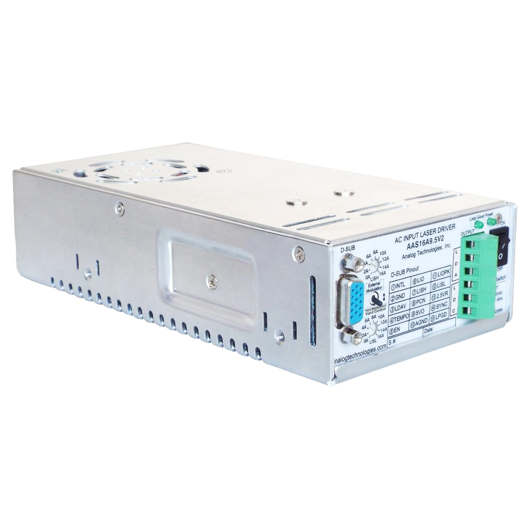
The constant-current set-point is controlled by a 0 V to 2.5 V analog signal. That signal can be sourced from the on-board internal potentiometer, an external potentiometer wired through the 15-pin D-Sub connector, or any external analog source (POT, DAC, or controller output) connected to the LISH/LISL pins. The 2.5 V reference voltage required to drive an external POT or DAC is provided on the 2.5VR pin.
What protection features safeguard the laser diode?
Each AAS-series driver integrates multiple protection layers: a hardware INTL safety-interlock input, an EN enable/disable input, soft-start during power-up, output short-circuit protection that cuts the output when a fault is detected, an over-temperature protection circuit that shuts the driver down at 85 °C and auto-restarts when temperature returns to range, and real-time control-loop monitoring via the LPGD pin that drives a Loop-Good LED whenever the constant-current loop is regulating correctly. The AAS45A4V2 additionally exposes a configurable output voltage limit for true constant-voltage compliance behaviour.
Are AAS drivers suitable for pulsed or LiDAR applications?
The AAS series supports digital on/off modulation up to 5 kHz via the PCN pin, with approximately 56 μs output current rise/fall time. This is sufficient for low-frequency pulsed applications, but not for true pulsed-mode LiDAR emitters that need peak currents hundreds to thousands of times the continuous limit at MHz pulse rates. For those, a dedicated pulsed-mode laser driver should be used instead.
What is the output ripple specification, and how is it different from the 354 μA figure?
Two distinct noise specifications are characterized in the AAS datasheets and should not be confused.
(1) Output ripple voltage at the 600 kHz PWM switching frequency: typically 8 mV
P-P, maximum 10 mV
P-P (measured at V
IN = 110 VAC, V
OUT = 2.5 V to 5 V, I
OUT = 15 A or 20 A depending on the model).
(2) Low-frequency output current corner noise integrated over the 0.1–10 Hz band: typically 354 μA
P-P (range 348–360 μA
P-P). The corner noise is specified on the AAS12A12V2, AAS16A9.5V2, AAS25A6V2, AAS40A4V2, AAS26A10V, and AAS50A6V3; the AAS45A4V2 datasheet does not specify this parameter. For applications requiring further attenuation of the 600 kHz residual, the external
ATLF20A5V ripple-noise filter can be inserted in series with the output.