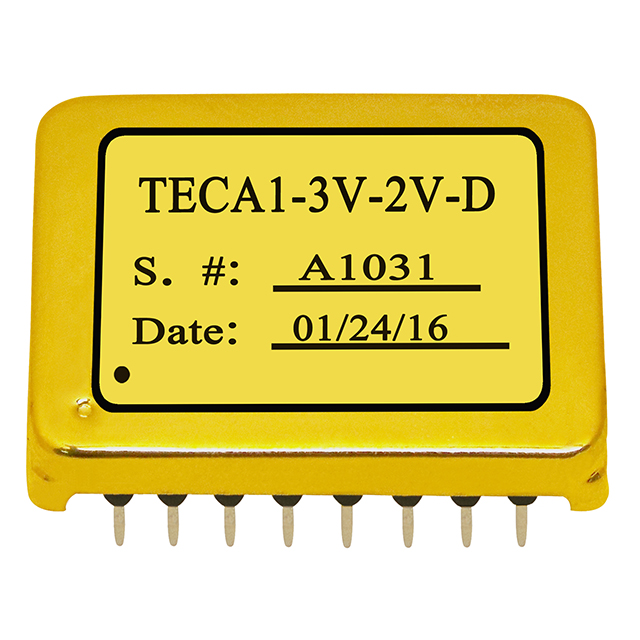
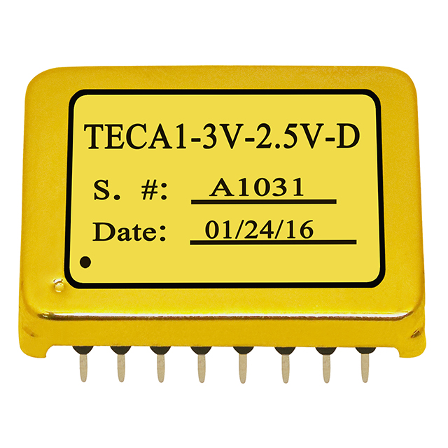
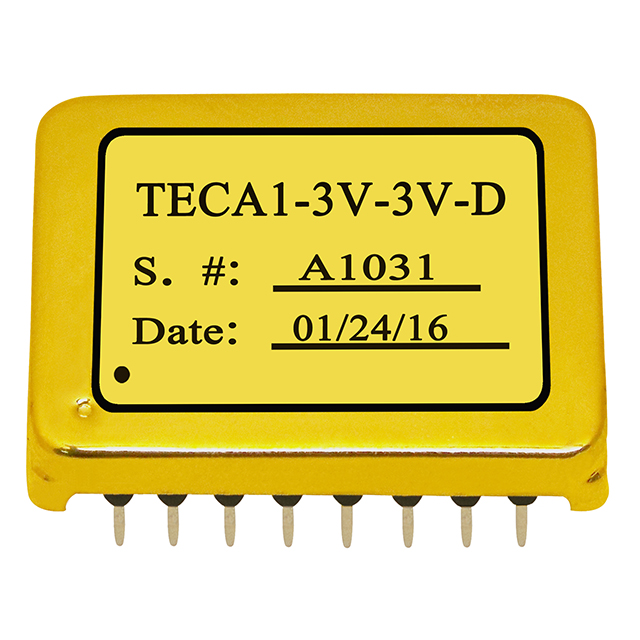
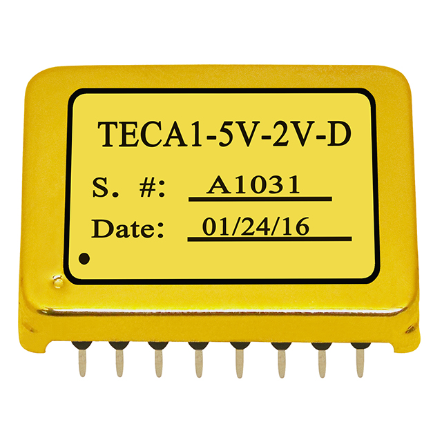
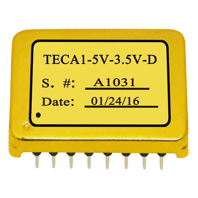
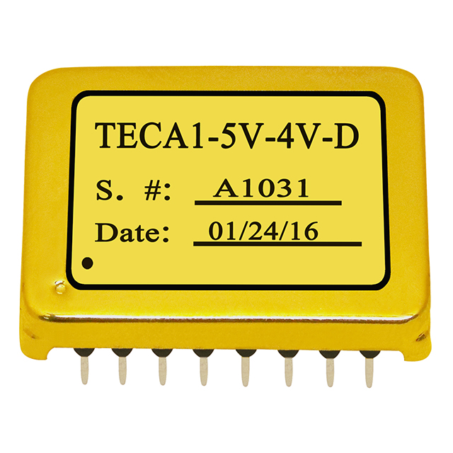
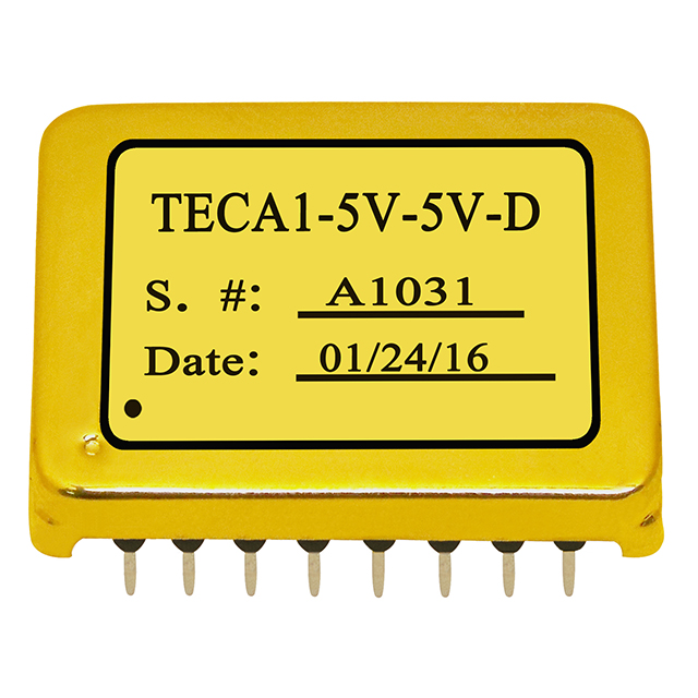
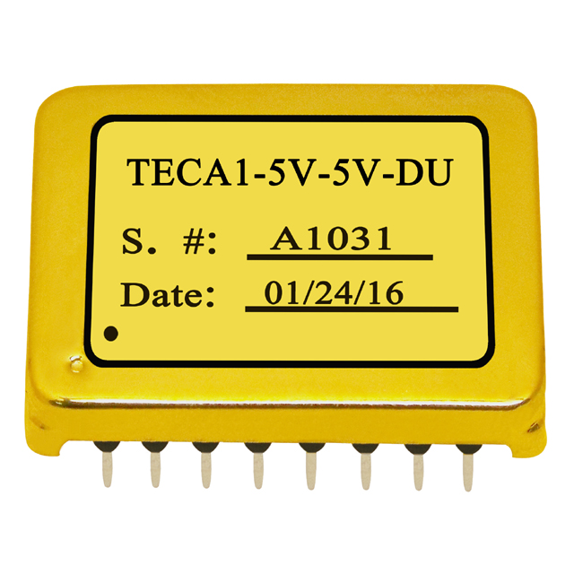
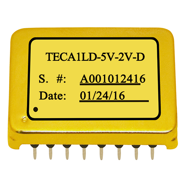
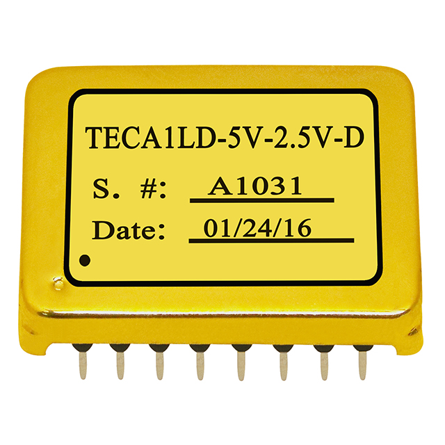
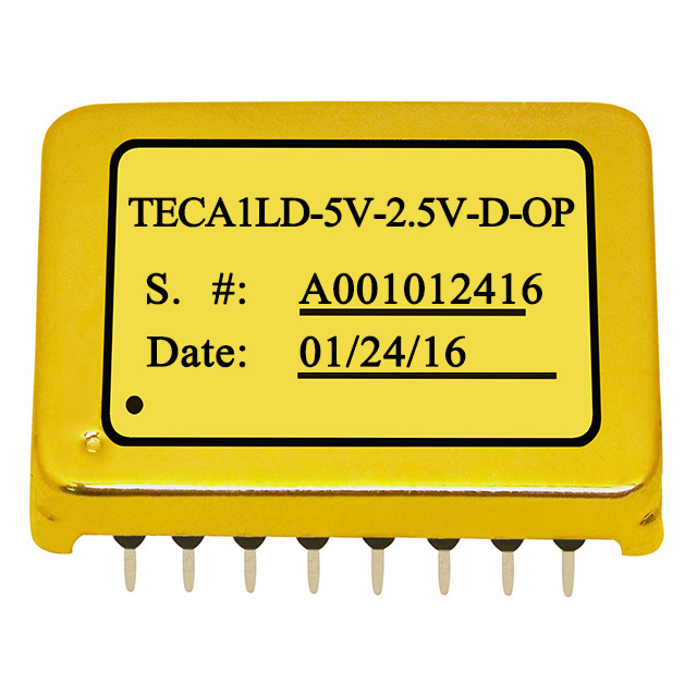
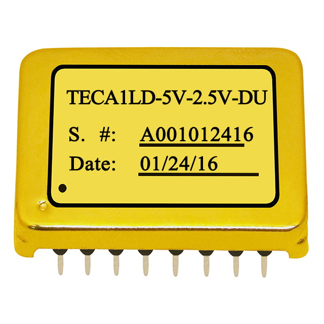
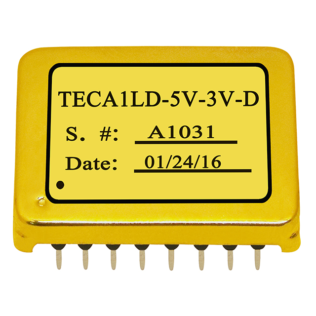
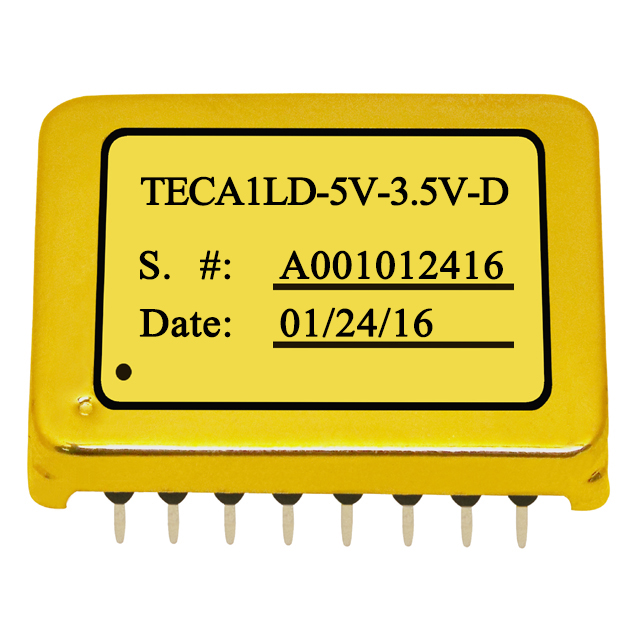
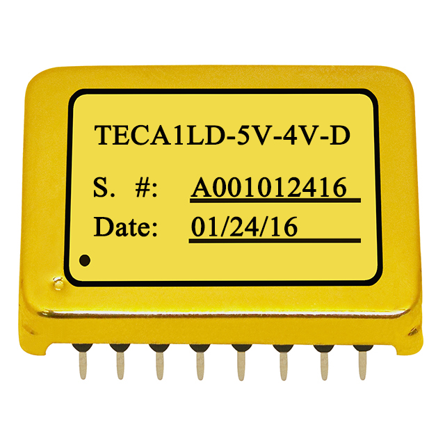
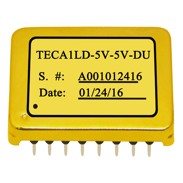
TECA1 Series TEC Controllers – 2.5A Thermoelectric Cooler (Peltier) Controller Modules

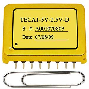
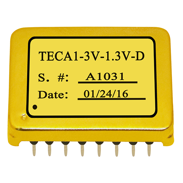
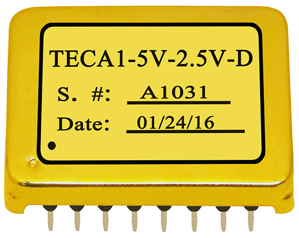
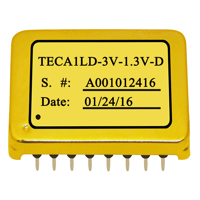
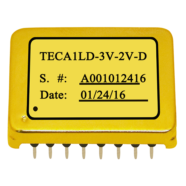
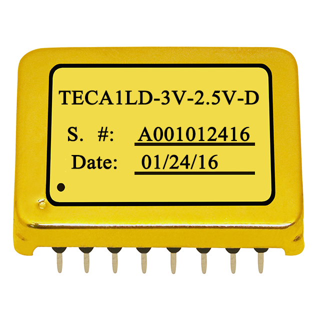
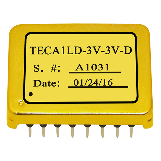
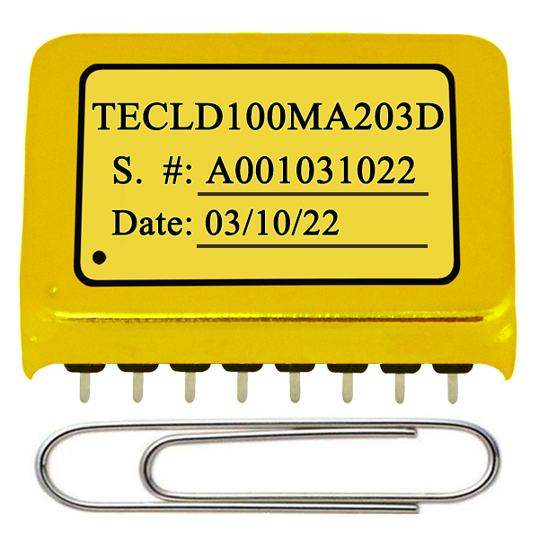
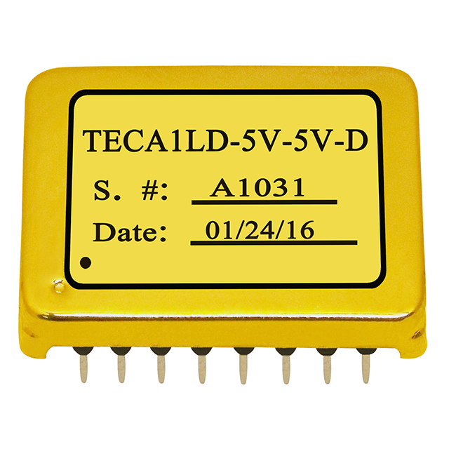
TECA1 series TEC controller module, gold plated 16-pin DIP package, 2.5A output

MAIN FEATURES

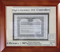
High Efficiency: ≥90%

Maximum Output Current: 2.5A

Actual Object Temperature Monitoring

High Temperature Stability: 0.01°C

Vacuum Potted and Low Outgassing

Gold Plated for High Reliability and Zero EMI

Compact Size: 25.4×19.9×4.5(mm), 16-Pin DIP

100 % lead (Pb)-free and RoHS compliant

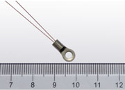
APPLICATIONS

The TECA1-xV-xV-D is a compact, gold-plated electronic module designed for driving TECs (Thermo-Electric Coolers) with a minimum of external components, achieving high stability in regulating the actual object temperature, high energy efficiency, zero EMI, and a small package. The target object is typically a metal plate on which a laser diode or an optical component is mounted; the default compensation network matches the TEC thermal load found in butterfly-packaged lasers. Because the module is vacuum potted and low-outgassing, it is also suitable for space applications. It can also be used to drive a resistive heater.

Key Specifications of TECA1 Series TEC Controllers

ParameterTest ConditionValueUnit
Target object* temp. stability vs. ambient temperatureVmaxTEC = 5V, RLoad = 2Ω0.0002°C/°C
Offset object temperature vs. set-point temperatureTAmbient is 0 – 50°C, set-point temp. is 15 – 35°C±0.1°C or ±5mV
Object temperature response time0.1 to the set-point temperature at a 1°C step<5s
EfficiencyVVPS = 5V, RLoad = 2Ω90%
Max. output currentVVPS = 5V, RLoad = 2Ω2.5A
Max. output voltageVVPS = 5V, RLoad = 2Ω0 – VVPSV
PWM frequency500kHz
Power supply voltage3.2 – 3.5 or 4.5 – 5.5 (typically 3.3 or 5)V
Set-point temp.** control voltageVVPS = 5V, RLoad = 2Ω0.1 – VVPSV
Default set-point temp. range***VVPS = 3V15 – 35°C
Operating temp. rangeVVPS = 5V, RLoad = 2Ω−40 – 85°C

Characteristics measured at TAmbient = 25°C and VVPS = 5V.
* Target object temperature refers to the actual temperature of the object mounted on the cold side of the TEC, whose temperature is regulated by the TEC controller.
** Set-point temperature is the desired temperature for the target object.
*** Can be customized to almost any range, provided the TEC has enough thermal power to achieve the range.
**** This TEC controller can only drive TECs with >1Ω impedance, which can be calculated by VMAX/IMAX. Maximum allowed input voltage of the controller: 6V.

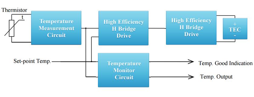
TECA1-XV-XV-D TEC controller functional block diagram: thermistor amplifier, error amplifier, compensation network, high efficiency H-bridge output stage

Selection Guide for TECA1 Series TEC Controllers

We can design and manufacture customized products based on customers' requirements.
Image Part Number Data-
sheet
Unit
Price
Qty.
Avail.
Buy
Now
Input
Voltage
Max.
Output
Voltage
Internal
Comp.
Network
Temp Pin @ Shut Down Package
Type
TECA1-3V-1.3V-D TEC controller module, 16-pin DIP TECA1-3V-1.3V-D
TEC controller
TECA1-3V-1.3V-D datasheet PDF $79 5 Buy TECA1-3V-1.3V-D TEC controllerBuy TECA1-3V-1.3V-D at SMTzone 3.3V 1.3V No Working DIP
TECA1-3V-2V-D TEC controller module, 16-pin DIP TECA1-3V-2V-D
TEC controller
TECA1-3V-2V-D datasheet PDF $79 9 Buy TECA1-3V-2V-D TEC controllerBuy TECA1-3V-2V-D at SMTzone 3.3V 2V No Working DIP
TECA1-3V-2.5V-D TEC controller module, 16-pin DIP TECA1-3V-2.5V-D
TEC controller
TECA1-3V-2.5V-D datasheet PDF $79 0 Buy TECA1-3V-2.5V-D TEC controllerBuy TECA1-3V-2.5V-D at SMTzone 3.3V 2.5V No Working DIP
TECA1-3V-3V-D TEC controller module, 16-pin DIP TECA1-3V-3V-D
TEC controller
TECA1-3V-3V-D datasheet PDF $79 5 Buy TECA1-3V-3V-D TEC controllerBuy TECA1-3V-3V-D at SMTzone 3.3V 3V No Working DIP
TECA1-5V-2V-D TEC controller module, 16-pin DIP TECA1-5V-2V-D
TEC controller
TECA1-5V-2V-D datasheet PDF $79 26 Buy TECA1-5V-2V-D TEC controllerBuy TECA1-5V-2V-D at SMTzone 5V 2V No Working DIP
TECA1-5V-2.5V-D TEC controller module, 16-pin DIP TECA1-5V-2.5V-D
TEC controller
TECA1-5V-2.5V-D datasheet PDF $79 63 Buy TECA1-5V-2.5V-D TEC controllerBuy TECA1-5V-2.5V-D at SMTzone 5V 2.5V No Working DIP
TECA1-5V-2.5V-D-OP TEC controller module, 16-pin DIP TECA1-5V-2.5V-D-OP
TEC controller
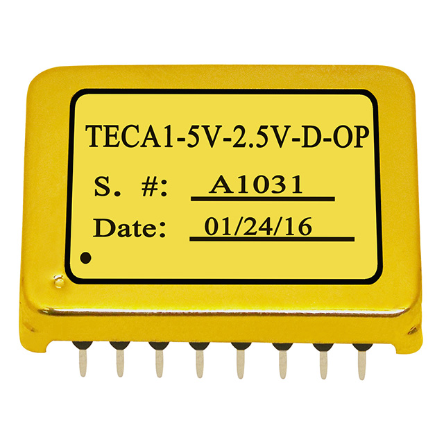
TECA1-5V-2.5V-D-OP datasheet PDF $79 0 Buy TECA1-5V-2.5V-D-OP TEC controllerBuy TECA1-5V-2.5V-D-OP at SMTzone 5V 2.5V No Working DIP
TECA1-5V-2.5V-DU TEC controller module, 16-pin DIP TECA1-5V-2.5V-DU
TEC controller
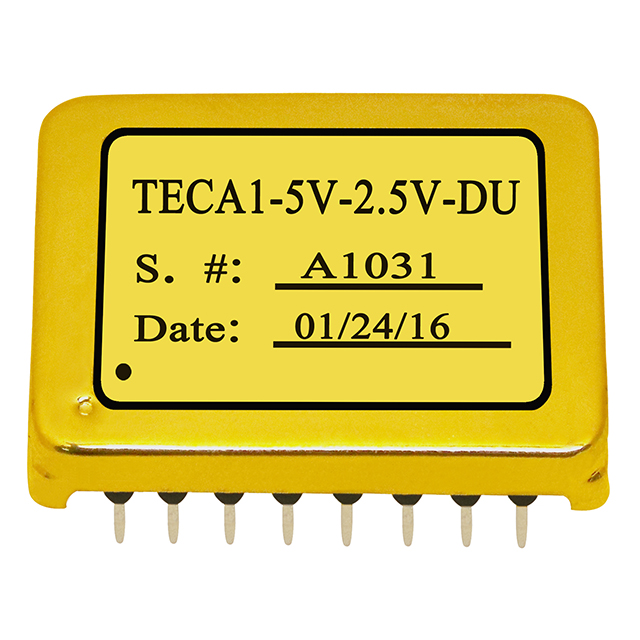
TECA1-5V-2.5V-DU datasheet PDF $79 0 Buy TECA1-5V-2.5V-DU TEC controllerBuy TECA1-5V-2.5V-DU at SMTzone 5V 2.5V No Working DIP
TECA1-5V-3V-D TEC controller module, 16-pin DIP TECA1-5V-3V-D
TEC controller
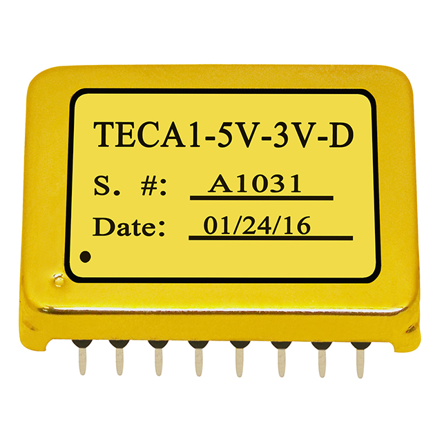
TECA1-5V-3V-D datasheet PDF $79 0 Buy TECA1-5V-3V-D TEC controllerBuy TECA1-5V-3V-D at SMTzone 5V 3V No Working DIP
TECA1-5V-3.5V-D TEC controller module, 16-pin DIP TECA1-5V-3.5V-D
TEC controller
TECA1-5V-3.5V-D datasheet PDF $79 7 Buy TECA1-5V-3.5V-D TEC controllerBuy TECA1-5V-3.5V-D at SMTzone 5V 3.5V No Working DIP
TECA1-5V-4V-D TEC controller module, 16-pin DIP TECA1-5V-4V-D
TEC controller
TECA1-5V-4V-D datasheet PDF $79 0 Buy TECA1-5V-4V-D TEC controllerBuy TECA1-5V-4V-D at SMTzone 5V 4V No Working DIP
TECA1-5V-5V-D TEC controller module, 16-pin DIP TECA1-5V-5V-D
TEC controller
TECA1-5V-5V-D datasheet PDF $79 14 Buy TECA1-5V-5V-D TEC controllerBuy TECA1-5V-5V-D at SMTzone 5V 5V No Working DIP
TECA1-5V-5V-DU TEC controller module, 16-pin DIP TECA1-5V-5V-DU
TEC controller
TECA1-5V-5V-DU datasheet PDF $79 0 Buy TECA1-5V-5V-DU TEC controllerBuy TECA1-5V-5V-DU at SMTzone 5V 5V No Working DIP
TECA1LD-3V-1.3V-D TEC controller module, 16-pin DIP TECA1LD-3V-1.3V-D
TEC controller
TECA1LD-3V-1.3V-D datasheet PDF $79 0 Buy TECA1LD-3V-1.3V-D TEC controllerBuy TECA1LD-3V-1.3V-D at SMTzone 3.3V 1.3V Yes Working DIP
TECA1LD-3V-2V-D TEC controller module, 16-pin DIP TECA1LD-3V-2V-D
TEC controller
TECA1LD-3V-2V-D datasheet PDF $79 0 Buy TECA1LD-3V-2V-D TEC controllerBuy TECA1LD-3V-2V-D at SMTzone 3.3V 2V Yes Working DIP
TECA1LD-3V-2.5V-D TEC controller module, 16-pin DIP TECA1LD-3V-2.5V-D
TEC controller
TECA1LD-3V-2.5V-D datasheet PDF $79 0 Buy TECA1LD-3V-2.5V-D TEC controllerBuy TECA1LD-3V-2.5V-D at SMTzone 3.3V 2.5V Yes Working DIP
TECA1LD-3V-3V-D TEC controller module, 16-pin DIP TECA1LD-3V-3V-D
TEC controller
TECA1LD-3V-3V-D datasheet PDF $79 44 Buy TECA1LD-3V-3V-D TEC controllerBuy TECA1LD-3V-3V-D at SMTzone 3.3V 3V Yes Working DIP
TECA1LD-5V-2V-D TEC controller module, 16-pin DIP TECA1LD-5V-2V-D
TEC controller
TECA1LD-5V-2V-D datasheet PDF $79 0 Buy TECA1LD-5V-2V-D TEC controllerBuy TECA1LD-5V-2V-D at SMTzone 5V 2V Yes Working DIP
TECA1LD-5V-2.5V-D TEC controller module, 16-pin DIP TECA1LD-5V-2.5V-D
TEC controller
TECA1LD-5V-2.5V-D datasheet PDF $79 79 Buy TECA1LD-5V-2.5V-D TEC controllerBuy TECA1LD-5V-2.5V-D at SMTzone 5V 2.5V Yes Working DIP
TECA1LD-5V-2.5V-D-OP TEC controller module, 16-pin DIP TECA1LD-5V-2.5V-D-OP
TEC controller
TECA1LD-5V-2.5V-D-OP datasheet PDF $79 0 Buy TECA1LD-5V-2.5V-D-OP TEC controllerBuy TECA1LD-5V-2.5V-D-OP at SMTzone 5V 2.5V Yes Working DIP
TECA1LD-5V-2.5V-DU TEC controller module, 16-pin DIP TECA1LD-5V-2.5V-DU
TEC controller
TECA1LD-5V-2.5V-DU datasheet PDF $79 0 Buy TECA1LD-5V-2.5V-DU TEC controllerBuy TECA1LD-5V-2.5V-DU at SMTzone 5V 2.5V Yes Working DIP
TECA1LD-5V-3V-D TEC controller module, 16-pin DIP TECA1LD-5V-3V-D
TEC controller
TECA1LD-5V-3V-D datasheet PDF $79 24 Buy TECA1LD-5V-3V-D TEC controllerBuy TECA1LD-5V-3V-D at SMTzone 5V 3V Yes Working DIP
TECA1LD-5V-3.5V-D TEC controller module, 16-pin DIP TECA1LD-5V-3.5V-D
TEC controller
TECA1LD-5V-3.5V-D datasheet PDF $79 15 Buy TECA1LD-5V-3.5V-D TEC controllerBuy TECA1LD-5V-3.5V-D at SMTzone 5V 3.5V Yes Working DIP
TECA1LD-5V-4V-D TEC controller module, 16-pin DIP TECA1LD-5V-4V-D
TEC controller
TECA1LD-5V-4V-D datasheet PDF $79 0 Buy TECA1LD-5V-4V-D TEC controllerBuy TECA1LD-5V-4V-D at SMTzone 5V 4V Yes Working DIP
TECA1LD-5V-5V-D TEC controller module, 16-pin DIP TECA1LD-5V-5V-D
TEC controller
TECA1LD-5V-5V-D datasheet PDF $79 19 Buy TECA1LD-5V-5V-D TEC controllerBuy TECA1LD-5V-5V-D at SMTzone 5V 5V Yes Working DIP
TECA1LD-5V-5V-DU TEC controller module, 16-pin DIP TECA1LD-5V-5V-DU
TEC controller
TECA1LD-5V-5V-DU datasheet PDF $79 0 Buy TECA1LD-5V-5V-DU TEC controllerBuy TECA1LD-5V-5V-DU at SMTzone 5V 5V Yes Working DIP

Input voltage: 3.2 – 3.5V for the "3V" parts and 4.5 – 5.5V for the "5V" parts (typically 3.3V and 5V); maximum allowed input voltage is 6V. The LD part numbers come with the thermal-loop compensation network embedded inside the controller (Yes); the part numbers without LD do not have it (No), and an external compensation network is required for the controller to operate. Unit price is for single quantity — contact sales@analogti.com for volume pricing.

Suffix Definition:

-D: For example: TECA1-3V-1.3V-D. The controller comes with DIP package.

U: For example: TECA1-5V-2.5V-DU. The controller only has cooling function, cannot do heating.

LD: For example: TECA1LD-5V-4V-D. The controller comes with an internal compensation network.

-OP: For example: TECA1-5V-2.5V-D-OP. The controller does not have the two 100kΩ pulling-to-the-middle resistors on the TEMPSP pin, as opposed to the controllers that do have these two resistors. In the standard controllers these two resistors are equivalent to a 50kΩ resistor to a 1.5V source, so an unconnected TEMPSP pin settles at 1.5V, corresponding to 25°C. See the datasheet for details.

Pin Functions and Design Notes

Pin Functions of the 16-Pin DIP Package
PinNameTypeDescription
1TEMPGDDigital outputPulled up to VPS by a 130Ω resistor when the controller is working and the target object temperature is within 0.1°C of the set-point value, or within 5mV difference between the voltages on the TEMP and TEMPSP pins; otherwise it is pulled down to GND by a 90Ω resistor. It can drive an LED as an indication that the thermal loop is stabilized.
23VRAnalog outputOutputs a 3V low-noise, highly stable reference voltage for a POT or DAC. Maximum sourcing current 1.5mA, maximum sinking current 4mA, stability <50ppm/°C max.
3TEMPSPAnalog inputSets the target object temperature from 0.1V to 3V, corresponding linearly to 15°C to 35°C. Internally connected to 1.5V by a 50kΩ resistor, so leaving it unconnected gives 1.5V, corresponding to 25°C. The lower limit for setting this pin is 0.1V; it can also be set to a voltage 0.2V below the VPS rail.
4GNDGroundSignal ground for the POT, ADC, DAC and the thermistor.
5TECCRTAnalog input and outputTEC control voltage. It can be left unconnected, or used to control the TEC voltage directly: set TECCRT between 0V and VVPS, then TEC voltage = VVPS − 2×VTECCRT. It can also configure the maximum voltage across the TEC: max. TEC voltage = VTECmax × Rm/(Rm+10k). The output impedance of this pin is 5kΩ.
6VTECAnalog outputTEC voltage indication: TEC voltage = VTECmax × (1 − 2×VVTEC/VVPS). The maximum driving current of this pin is 30mA and the output voltage swing is 0V to VVPS.
7CMINAnalog inputCompensation input pin for the thermal control loop. Connect the compensation network to this pin, or leave it unconnected if the controller has an internal compensation network already. This pin is noise sensitive: do not connect it with a long wire or a long PCB trace.
8TEMPAnalog outputActual target object temperature indication. It swings from 0V to VVPS. With the default internal temperature network, 0V to 3V represents 15°C to 35°C linearly; 0V to 5V represents 15°C to 50°C.
9SDNGDigital inputShut-down control. Pulling it to <0.8V shuts down the controller; leaving it unconnected or pulling it >1.8V activates the controller. Internally pulled up to VPS by a 100kΩ resistor. The maximum input voltage range allowed on this pin is 0V to 6V. Quiescent current: 45mA before shutting down, 26mA after the TECNEG output stage is shut down, 6mA once the TECPOS output stage is also shut down.
10GNDGroundSignal ground; can also be used for the return path of the thermistor.
11RTHAnalog inputThermistor input port, to sense the target object temperature. With the default temperature network, the thermistor is expected to be 10kΩ @ 25°C. ATI recommends its own ATH10K1R25 NTC thermistor.
12TECPOSAnalog power outputTEC positive pin, for connecting to the TEC's positive terminal.
13TECNEGAnalog power outputTEC negative pin, for connecting to the TEC's negative terminal.
14PGNDPower groundPower ground, for connecting to the return rail of the power supply.
15PGNDPower groundThe same as pin 14, and internally connected with it.
16VPSPower inputPositive power supply rail. Two possible values: 3.3V and 5V, depending on the module.
Compensation Network, Thermistor, Customization and Handling Notes

Thermal loop compensation network

The compensation network for the thermal control loop consists of five components: three resistors and two capacitors. It can be implemented internally, inside the controller enclosure (part numbers with the LD suffix), or externally on the PCB (part numbers without LD). The external network is highly recommended, since it can be modified for driving different thermal loads, and the thermal load characteristics may not be fixed at the early design stage. The default values, which match the TEC thermal load found in butterfly-packaged lasers, are Rd = 100kΩ, Ri = 301kΩ, Rp = 301kΩ, Cd = 2.2µF and Ci = 4.7µF.

Thermistor and set-point temperature

The controller comes with a default temperature setting network based on a 10kΩ @ 25°C thermistor. To change the set-point temperature outside the default range, an external resistor can be combined with the thermistor so that the total equals 10kΩ at the target temperature. For example, at 4°C the thermistor is about 25kΩ; add a parallel resistor so the total resistance is 10kΩ, then set TEMPSP to 1.5V and the actual set-point temperature will be about 4°C. At 37°C the thermistor is about 5kΩ; put an external 5kΩ resistor in series, then set TEMPSP to 1.5V and the set-point temperature will be about 37°C. When using a different thermistor and/or a different set-point range, contact us and we will configure the internal temperature network for you.

Customizations

  • Maximum output voltage across the TEC. The part number becomes TECA1-5V-(max. TEC voltage)-D, e.g. TECA1-5V-2.5V-D.
  • Set-point temperature range. Specify the lower limit (TEMPSP = 0V), the upper limit (TEMPSP = 3V) and the open-circuit temperature (TEMPSP = 1.5V or unconnected), e.g. TECA1-5V-2.5V-D (20/80/50).
  • Asymmetrical maximum TEC voltage — different limits for cooling and heating, e.g. TECA1-5V-2.5V/1.5V-D.

Contact sales@analogti.com · Tel. 408-748-9100.

Handling notes

WARNING: This controller module can only be soldered manually onto the board by a solder iron at <310°C (590°F); it cannot go through a reflow oven process.

NOTE: The power supply may overshoot and exceed the maximum allowed input voltage of the controller, 6V, damaging it permanently. Connect the controller solidly to the power supply before turning on the power; make sure the power supply can supply 1.2 to 1.5 times the maximum current the controller requires; when using a bench-top power supply, set the current limit to >1.5 times that maximum.


Note:

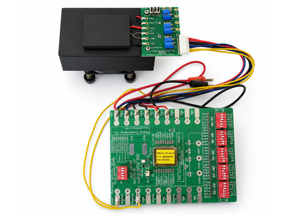
Evaluation Board, TECEV104, is available for TEC controllers TECA1-xV-xV-D, which can be used for achieving the following functions:

1. Setting maximum output voltage
2. Setting set-point temperature

3. Monitoring output voltage

4. Monitoring actual thermal load temperature

5. Tuning the compensation network so as to match thermal load

Related ATI TEC Controllers

Part #VINVOUTDimensions (mm)Difference
TEC14M5V3R5AS2.7V – 5.5V±VVPS14.0×14.0×2.2Micro TEC controller
TEC5V6A-D / TEC5V4A-D4.5V – 5.5V±VVPS25.4×19.9×8.8TECNEG: linear; TECPOS: filtered PWM. Max. |VTEMP − VTEMPSP| ≤ 5mV (-DA: ≤ 2mV; -DAH: ≤ 0.5mV)
TEC18V15A6.0V – 18V±15V35.7×35.7×7.2High voltage, high current, with embedded firmware inside
TEC50V20ACH12V – 50V±40V63.0×61.0×16.7High voltage, high current — under development
TECA2-XV-XV-DAH4.5V – 5.5V±VVPS20.14×14.6×8.0Smaller size; TEMP pin remains off @ SDNG = 0 — under development

See the full ATI TEC / Peltier controller line.

Frequently Asked Questions

What supply voltage does a TECA1 TEC controller need?

3.2 – 3.5V for the "3V" parts, or 4.5 – 5.5V for the "5V" parts (typically 3.3V or 5V). The maximum allowed input voltage of the controller is 6V, so guard against power supply overshoot at turn-on.

What size TEC can the TECA1 drive?

Up to 2.5A, with a maximum output voltage from 0 to VVPS. The TEC impedance must be greater than 1Ω, calculated as VMAX/IMAX.

What is the difference between TECA1 and TECA1LD?

TECA1LD has the thermal-loop compensation network embedded inside the module, with default values that match the TEC thermal load found in butterfly-packaged lasers. TECA1 without the LD suffix has no internal compensation network, so an external network of three resistors and two capacitors is required, and it can be re-tuned for a different thermal load.

Which thermistor should I use with the TECA1?

A 10kΩ @ 25°C NTC thermistor. ATI recommends the ATH10K1R25.

How accurate is the temperature control?

The offset between the object temperature and the set-point temperature is ±0.1°C (or ±5mV between TEMP and TEMPSP) over an ambient of 0 – 50°C, and the object temperature drifts only 0.0002°C per °C of ambient change.

Is there an evaluation board for the TECA1?

Yes — the TECEV104. It is used for setting the maximum output voltage and the set-point temperature, monitoring the output voltage and the actual thermal load temperature, and tuning the compensation network to match the thermal load.

RELATED PRODUCTS: