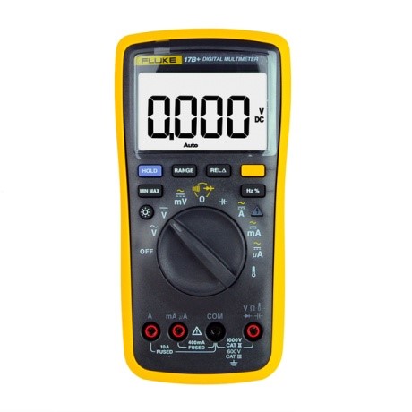
Digital multimeter is one of the entry-level tools for electronic engineers. Take
FLUKE F17B+ as an example to show you how we use this multimeter.
FLUKE digital multimeter is one of the best multimeters that you can buy. It can measure DC and AC voltages, current, resistance, continuity, capacitance, and temperature.
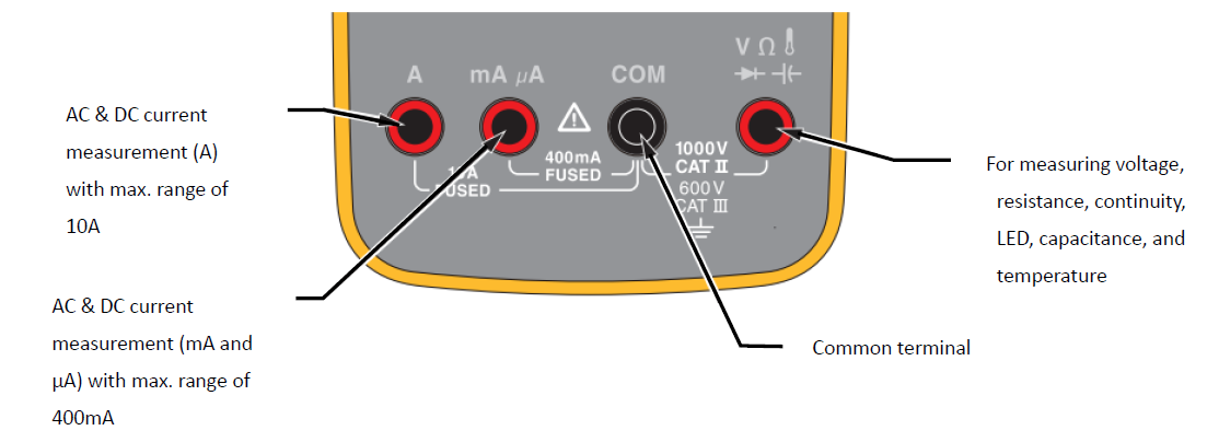
The black test lead is connected to the black input terminal "COM", and the red test lead is connected to different input terminals for corresponding measurements.
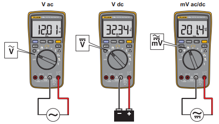
When measuring AC or DC voltage, connect the black test lead to "COM" and the red test lead to

.
Turn the rotary switch to the corresponding position (

) to select DC or AC.
Press

to toggle between mVAC and mVDC voltage measurement.
Touch the probes to the correct test points of the circuit (see the figure below) to measure the voltage. Read the voltage directly on the display.
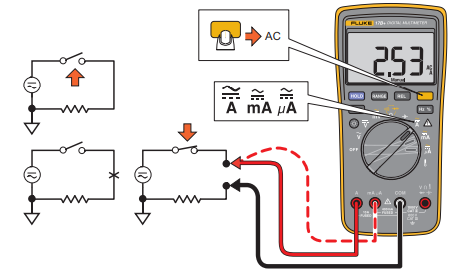
When measuring AC or DC current, connect the black test lead to "COM" and the red test lead to "A, mA, or μA".
Turn the rotary switch to the corresponding position (

) to select DC or AC.
Press

to toggle between AC and DC current. Disconnect the circuit to be measured (for safety, cut off the power to the circuit at first), and connect the multimeter in series to the circuit.
Note the direction of the two test leads (see the figure below). Apply the power of the circuit and read the current directly on the display screen.
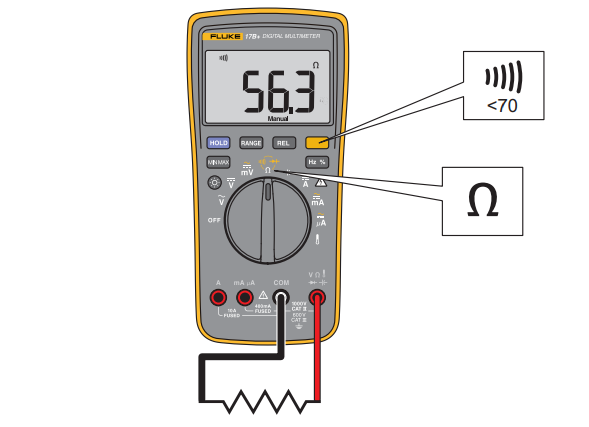
When measuring resistance, continuity, and LED, connect the black test lead to "COM" and the red test lead to
.
Turn the rotary switch to the corresponding position (

).
Disconnect the power of the circuit to be measured, and connect the probe to the correct test points of the circuit (see the figure below).
Then you can directly read the result on the display.
When selecting the resistance mode, press

once to activate the continuity beeper.
When the measured resistance is lower than 70Ω, the beeper will sound continuously, indicating a short circuit.
Press

twice to activate the function to measure diode.
Connect the red test lead to the anode of the diode, and the black test lead to the cathode of the diode.
The forward bias voltage can be read on the display.
If the polarity of the test lead is reversed with diode polarity, you can read

on the display.
This is used to distinguish the anode and cathode of a diode.
When measuring capacitance, connect the black test lead to "COM" and the red test lead to
.
Turn the rotary switch to the corresponding position (

).
The probe contacts the two leads of the capacitor. After the reading is stable (it may take up to 18 seconds), the capacitance value can be read directly on the display. The capacitor connected in the circuit is easy to be affected by other components in the circuit, which results in a large deviation of the capacitance value. If an accurate capacitance value is needed, it is recommended to measure the capacitor separately.
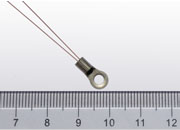
When measuring temperature, use it with a thermocouple (see the figure below). The plug marked with "-" is inserted into "COM", and the plug with "+" is inserted into
.
Then turn the switch to the corresponding position

.
Read the temperature on the display.
Press

to switch between °C and °F.

 , you can directly read the frequency on the display.