Product Catalog
- TEC/Peltier Controllers
- Laser Drivers
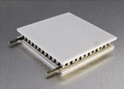
- TEC Modules
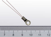
- Thermistors
- TEG
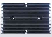
- Heat Sink
- Temperature Plate Assembly
- Thermal Conductive Material
- SMT/SMD Resistor Kits
- SMT/SMD Capacitor Kits
- SMT/SMD Inductor Kits
- Empty Enclosure
- Adjustable Decade Boxes
- LED Related Products
- Noise Measurement Amplifier
- High Voltage Power Supply
- Household Earthquake Alarm
- + More Products
- Videos
Company's Patents
|


Contact Us
Analog Technologies, Inc.
2352 Walsh Ave.
Santa Clara, CA 95051
U. S. A
Tel.: 408-748-9100
Fax: 408-748-9111

New Website: www.analogti.com
Online Store: www.smtzone.com
Selection and installation of TECs
Time : 2015-05-15 16:52Source :analogtechnologies Author : Analog Click :
In general, selecting the size of TECs depends on the area of chips, but not bigger than that. Additionally, TEC has a certain thickness, which is put between chip and heat sink. If it is too thick, it will be hard to fix.
Generally speaking, the operating temperature of TEC is about under 50℃, that is: CPU should work in the range of operating temperature. As the maximum temperature difference can be up to 65℃, if the hot end temperature is not over 65℃, in the limit case, the temperature of the cold end can reach 0℃ or even under 0℃.
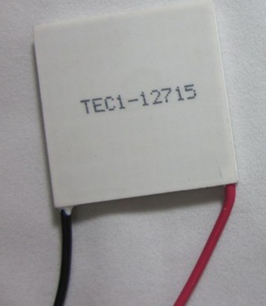
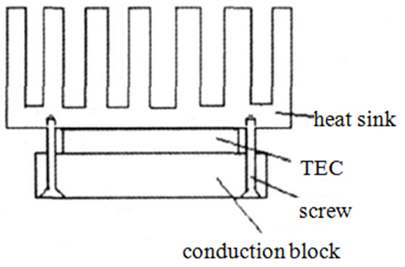
As shown in fig. 2, the TEC should be fixed according to the order of heat sink-TEC-CPU. Interface between TEC and the other two parts should be smeared with thermal grease, which can not only be useful to transmit heat, but also to buffer.
If you want to know more, please feel free to contact us.
Our web site is http://www.analogtechnologies.com/
Fig. 2. Physical photo of TEC
Generally speaking, the operating temperature of TEC is about under 50℃, that is: CPU should work in the range of operating temperature. As the maximum temperature difference can be up to 65℃, if the hot end temperature is not over 65℃, in the limit case, the temperature of the cold end can reach 0℃ or even under 0℃.
As shown in fig. 2, the TEC should be fixed according to the order of heat sink-TEC-CPU. Interface between TEC and the other two parts should be smeared with thermal grease, which can not only be useful to transmit heat, but also to buffer.
Fig. 2. Installation diagram of TEC
If you want to know more, please feel free to contact us.
Our web site is http://www.analogtechnologies.com/
Next : Installation of TECs in Thermo-electric Cooling System (II) Last : Installation of TECs in Thermo-electric Cooling System (I)
Hot news
- How to use the NTC
- Application Status of Semiconductor Lasers
- Functions of Capacitor Kits
- Reliability of thermoelectric cooler
- The Principle of NTC Thermistor
- The Features of Laser Drivers
- Heat Sink in Thermoelectric Cooling System
- The Definition of Low Niose Amplifier
- Resistor/capacitor/inductor kits
- Analysis of LED Market Prospects