Product Catalog
- TEC/Peltier Controllers
- Laser Drivers
- TEC Modules
- Thermistors
- TEG
- Heat Sink
- Temperature Plate Assembly
- Thermal Conductive Material
- SMT/SMD Resistor Kits
- SMT/SMD Capacitor Kits
- SMT/SMD Inductor Kits
- Empty Enclosure
- Adjustable Decade Boxes
- LED Related Products
- Noise Measurement Amplifier
- High Voltage Power Supply
- Household Earthquake Alarm
- + More Products
- Videos
Company's Patents
|


Contact Us
Analog Technologies, Inc.
2352 Walsh Ave.
Santa Clara, CA 95051
U. S. A
Tel.: 408-748-9100
Fax: 408-748-9111

New Website: www.analogti.com
Online Store: www.smtzone.com
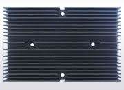
The heat resistance theory of heat sink
Time : 2015-05-29 11:20Source :analogtechnologies Author : Analog Click :
As shown figure 1, the heat flow ∅_0 goes through the bottom of heat sink and then goes into its root. In the root, the heat flow will be divided into two shares ∅_1and∅_2, and then through the root and environment air, start convection and heat exchange. Finally, the heat flow goes into the environment by heat exchange with fins. The heat resistance network model is shown in figure 1.


As the lateral area of heat sink base is much smaller than the root cross-sectional area, the heat dissipated from side can be omitted. The whole heat flow enters the bottom and side of heat sink by heat conduction. The heat transfer thermal resistance on the surface of fins is much larger than the heat conduction thermal resistance
  in the fins. So on the cross section at the constant height, the fin temperature can be considered uniform. The top of the fins can be regarded as insulation. The heat conduction coefficient
  , the surface heat transfer coefficient h and the cross section area Ac along the fin height are all constant.
According to the above simplification, the model established is a one-dimensional steady state heat conduction model and the equivalent thermal resistance of the rib fin is
Where, Rr— heat resistance of the heat dissipation part at the root, K / W;
Rf—heat resistance of the heat dissipation part in the side, K / W.
If you want to know more, please contact us.
Our web site is http://www.analogtechnologies.com/
Fig 1. The heat flow schematic diagram of heat sink dissipation
Fig 2. The heat resistance network model of fins
As the lateral area of heat sink base is much smaller than the root cross-sectional area, the heat dissipated from side can be omitted. The whole heat flow enters the bottom and side of heat sink by heat conduction. The heat transfer thermal resistance
on the surface of fins is much larger than the heat conduction thermal resistance in the fins. So on the cross section at the constant height, the fin temperature can be considered uniform. The top of the fins can be regarded as insulation. The heat conduction coefficient , the surface heat transfer coefficient h and the cross section area Ac along the fin height are all constant.According to the above simplification, the model established is a one-dimensional steady state heat conduction model and the equivalent thermal resistance of the rib fin is
Where, Rr— heat resistance of the heat dissipation part at the root, K / W;
Rf—heat resistance of the heat dissipation part in the side, K / W.
If you want to know more, please contact us.
Our web site is http://www.analogtechnologies.com/
Next : Thermoelectric cooler applied in the LED packaging Last : The structure of thermoelectric cooler
Hot news
- How to use the NTC
- Application Status of Semiconductor Lasers
- Functions of Capacitor Kits
- Reliability of thermoelectric cooler
- The Principle of NTC Thermistor
- The Features of Laser Drivers
- Heat Sink in Thermoelectric Cooling System
- The Definition of Low Niose Amplifier
- Resistor/capacitor/inductor kits
- Analysis of LED Market Prospects