Click here to download PDF version.
When designing a laser system, the first thing needed is to make decision: design a laser driver or use an off-the-shelf laser driver. Which way is better?
Design a Laser Driver vs. Using an Off-the-shelf Laser Driver
It is apparent that designing a laser driver will save money in the long run for high volume production laser systems. But the cost for this route is not low: high design cost, long design time, high risk to fail or result in sacrificed performance because designing a good laser driver requires years’ experience and many times failure, high initial cost for production set up and quality control, low reliability because it takes a lot of effort in production for high quality manufacturing, testing and burning-in. On the other hand, laser systems usually do not have high volume need before they are replaced by newer technologies or become obsolete because new optical systems have new sets of features and requirements. Therefore, for most applications, using off-the-shelf laser drivers might be the best way to go: it saves time and money, minimizes the risk and results in good performance.
How to Design a Laser Driver
Inside a laser driver, there are many electronic circuitries as shown in Figure 1. The first part of the circuit is always power supply protection. This circuit keeps the whole laser driver off when the power supply does not have enough voltage. It energizes the whole circuit when the input voltage exceeds a preset threshold value. This circuit also keeps the laser driver off when the input voltage is not stabilized. The last function is to filter out any noise the power supply voltage may have.
The next circuit below on the lower left corner is the signal processing and noise suppression. From the names it can tell that this circuit processes the input control signals to become a less noisy and gained up signals and sends them to the control circuit above. At the same time, the laser status signals, such as laser actual power, laser actual current, laser actual voltage, etc., are used to compare with the input parameter setting signals, such as laser set-point current, laser circuit limit, laser set-point power, etc., and the final differences are sent to the control circuit.
The control circuit receives the signals from the Signal Processing & Noise Suppression circuit, process them, and send them to the Output Stage. This circuit also receives signals from the Shutdown pin and the Stand-by signals.
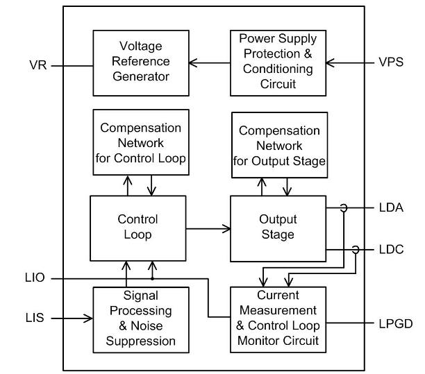
Figure 1. Block Diagram
How to Choose an Off-the-shelf Laser Driver
In order to choose a proper laser driver, we need to consider the following aspects:
1. Current, Voltage & Power
Before choosing an off-the-shelf laser driver, we need to ask some important questions, like what maximum current does the application require? What the maximum voltage does the power supply provide? What efficiency does the application need? These parameters are the basics for selecting a proper laser driver. It’s easy to know the maximum current and input voltage that the application requires. About the power consumption, please refer to the following.
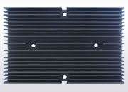
When the maximum power consumed by a linear controller is maintained to <1W, it does not require a heat sink to operate. The power dissipated by the laser driver can be calculated by this formula:
IVPS = IQ + IOUT
PIN = VPS´ IVPS
POUT = VOUT´ IOUT
PDR = PIN − POUT
= VPS ´ IQ + (VPS − VOUT) ´ IOUT
where, IVPS is the input current at the VPS node, VPS is the power supply voltage, IGND is the ground pin current, VOUT is the output voltage at the load, IOUT is the output current going through the load.
For switch mode laser driver, the power consumption cost by the laser driver is:
PIN = PDR + POUT
POUT = η ´ PIN ≈ 0.9PIN
PDR = 0.1PIN
η is various with working conditions, therefore, you would need to read datasheets for specific different η values on the different working conditions.
2. Linear Mode or Switch Mode
There are linear mode laser driver and switch mode laser driver. For linear type laser driver, it features low noise and high modulation speed, but it generates more heat because of its efficiency. There is an approach to reduce the heat dissipation: make the difference of VOUT and VIN as small as possible, which helps decrease the power loss.
Analog Technologies, Inc. (ATI) makes a wide variety of laser drivers, see the laser driver selection guide below:
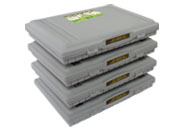
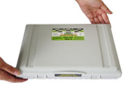
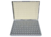
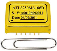
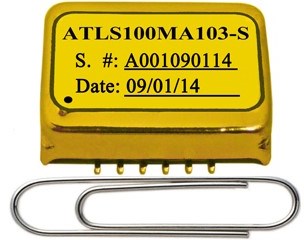
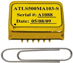
3. Styles
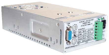
Laser driver can be an instrument or a module. The former generally comes with a front panel with buttons or knobs for users to adjust. Powered by AC power supply, these bench-top laser drivers usually come with a relatively large size. The latter is an electronic module, which can be mounted to a printed circuit board (PCB). Without any moving parts, these laser drivers come with a compact size and powered by DC power supply. The laser driver modules have two packaging types, DIP (Dual Inline Package) and SMT (Surface Mount). These modules save space and can be used in applications with limited space.
ATI makes different styles of laser drivers, see below:
| Part Number | Output Stage Type |
Control Mode |
Input Type | Description | VIN Range |
Max. IOUT |
VOUT Range |
Noise @0.1~10Hz |
Size (mm) |
|---|---|---|---|---|---|---|---|---|---|
| ATLS500MA212D | Switch mode | Constant current | DC |
High voltage & Constant current |
4.5V to 15V | 0.5A | 0V to 0.9×VPS | 10µA | 25.4×20×5 |
| ATLS1A212D | Switch mode | Constant current | DC |
High voltage & Constant current |
4.5V to 15V | 1A | 0V to 0.9×VPS | 12µA | 25.4×20×5 |
| ATLS2A212D | Switch mode | Constant current | DC | High efficiency | 4.5V to 15V | 2A | 0V to 0.9×VPS | 12µA | 25.4×20×5 |
| ATLS3A212D | Switch mode | Constant current | DC | High efficiency | 4.5V to 15V | 3A | 0V to 0.9×VPS | 10µA | 25.4×20×5 |
| ATLS4A214D | Switch mode | Constant current | DC | High efficiency | 5V to 14V | 4A | 0V to 0.75×VPS | 12µA | 27.4×21×5.7 |
| ATLS6A214D | Switch mode | Constant current | DC | High efficiency | 5V to 14V | 6A | 0V to 0.75×VPS | 12µA | 27.4×21×5.7 |
| ATLS8A216D |
Linear mode |
Constant current | DC | High efficiency | 5.5V to 15V | 8A | 0.8V to 0.8VPS | 12µA | 27.4×21×5.7 |
| ATLS10A216D |
Linear mode |
Constant current | DC | High efficiency | 5.5V to 15V | 10A | 0.8V to 0.8VPS | 12µA | 27.4×21×5.7 |
| ATLS250MA106 |
Linear mode |
Constant current | DC |
Constant current & |
3V to 5.5V | 0.25A | 1.5V to 4V | 4.5μAP-P | 20.14×14.6×5 |
| ATLS500MA106 |
Linear mode |
Constant current | DC |
Constant current & |
3V to 5.5V | 0.5A | 1.5V to 4V | 4.5μAP-P | 20.14×14.6×5 |
| CWD-01-V2-D | Switch mode | Constant current | DC | High efficiency | 3.0V to 5.5V | 2A | 0V to 0.9×VPS | 25μAP-P | 25.8×20×5 |
| ATLS500MA201D | Switch mode | Constant current | DC |
High efficiency Same pinout as CWD-01-V2-D |
3.0V to 5.5V | 0.5A | 0V to 0.9×VPS | 25μAP-P | 25.8×20×5.0 |
| ATLS1A201D | Switch mode | Constant current | DC |
High efficiency Same pinout as CWD-01-V2-D |
3.0V to 5.5V | 1A | 0V to 0.9×VPS | 25μAP-P | 25.8×20×5.0 |
| ATLS2A201D | Switch mode | Constant current | DC |
High efficiency Same pinout as CWD-01-V2-D |
3.0V to 5.5V | 2A | 0V to 0.9×VPS | 25μAP-P | 25.8×20×5.0 |
| ATLS3A201D | Switch mode | Constant current | DC |
High efficiency Same pinout as CWD-01-V2-D |
3.0V to 5.5V | 3A | 0V to 0.9×VPS | 25μAP-P | 25.8×20×5 |
| ATLS4A201D | Switch mode | Constant current | DC |
High efficiency Same pinout as CWD-01-V2-D |
3.0V to 5.5V | 4A | 0V to 0.9×VPS | 25μAP-P | 25.8×20×5 |
| ATLS6A201D | Switch mode | Constant current | DC |
High efficiency Same pinout as CWD-01-V2-D |
3.0V to 5.5V | 6A | 0V to 0.90×VPS | 25μAP-P | 25.8×20×5 |
| ATLS500mA202D | Switch mode | Constant current | DC |
High efficiency Same pinout as CWD-01-V2-D |
3.0V to 5.5V | 0.5A | 0V to 0.90×VPS | 25μAP-P | 25.8×20×5 |
| ATLS1A202D | Switch mode | Constant current | DC |
High efficiency Same pinout as CWD-01-V2-D |
3.0V to 5.5V | 1A | 0V to 0.90×VPS | 25μAP-P | 25.8×20×5 |
| ATLS2A202D | Switch mode | Constant current | DC |
High efficiency Same pinout as CWD-01-V2-D |
3.1V to 6.0V | 2A | 0V to 0.90×VPS | 25μAP-P | 25.8×20×5 |
| ATLS3A202D | Switch mode | Constant current | DC |
High efficiency Same pinout as CWD-01-V2-D |
3.0V to 5.5V | 3A | 0V to 0.90×VPS | 25μAP-P | 25.8×20×5 |
| ATLS4A202D | Switch mode | Constant current | DC |
High efficiency Same pinout as CWD-01-V2-D |
3.0V to 5.5V | 4A | 0V to 0.90×VPS | 25μAP-P | 25.8×20×5 |
| ATLS6A202D | Switch mode | Constant current | DC |
High efficiency Same pinout as CWD-01-V2-D |
3.0V to 5.5V | 6A | 0V to 0.90×VPS | 25μAP-P | 25.8×20×5 |
| LDA1-CP1 | Switch mode |
Constant current & Constant power |
DC |
High efficiency & PD anode grounded |
3.0V to 5.5V | 2A | 0V to 0.9×VPS | 25μAP-P | 25.4×20×4.6 |
| LDA1-CP2 | Switch mode |
Constant current & Constant power |
DC |
High efficiency & PD anode not grounded |
3.0V to 5.5V | 2A | 0V to 0.9×VPS | 25μAP-P | 25.4×20×4.6 |
| ATLS1A102 | Linear mode |
Constant current LDC = 0.5V |
DC | Low noise: <10uA | 3.0V to 5.5V | 1A | 0V to VPS-1V | 10μAP-P | 19.4×14.5×5 |
| ATLS100MA103 | Linear mode |
Constant current Rise time: 300ns LDC = 0V |
DC | Low noise: 1.5µAP-P | 3.0V to 5.5V | 0.1A | 0V to VPS-1V | 1.5µAP-P | 20×14.5×5 |
| ATLS200MA103 | Linear mode |
Constant current Rise time: 300ns LDC = 0V |
DC | Low noise: 2.5µAP-P | 3.0V to 5.5V | 0.2A | 0V to VPS-1V | 2.5µAP-P | 20×14.5×5 |
| ATLS250MA103 | Linear mode |
Constant current Rise time: 300ns LDC = 0V |
DC | Low noise: 2.5µAP-P | 3.0V to 5.5V | 0.25A | 0V to VPS-1V | 2.5µVP-P | 20×14.5×5 |
| ATLS500MA103 | Linear mode |
Constant current Rise time: 300ns LDC = 0V |
DC | Low noise: 5μAP-P | 3.0V to 5.5V | 0.5A | 0V to VPS-1V | 5μAP-P | 20×14.5×5 |
| ATLS1A103 | Linear mode |
Constant current Rise time: 300ns LDC = 0V |
DC | Low noise: 6µAP-P | 3.0V to 5.5V | 1A | 0V to VPS-1V | 6µAP-P | 20×14.5×5 |
| ATLS500MA104 |
Linear mode |
Constant current | DC | Low noise: 3.96µAP-P | 4.75V~5.75V | 0.5A | 3.1V~5.5V | 3.96µAP-P | 20.14×16.8×5 |
| AAS12A12V | Switch mode | Constant current | AC | High efficiency | 100VAC to 240VAC | 12A | 0V to 12V | 354μAP-P | 199×99×50 |
| AAS16A9.5V2 | Switch mode | Constant current | AC | High efficiency | 100VAC to 240VAC | 16A | 0V to 9.5V | 354μAP-P | 199×99×50 |
| AAS25A6V | Switch mode | Constant current | AC | High efficiency | 100VAC to 240VAC | 25A | 0V to 6V | 354μAP-P | 199×99×50 |
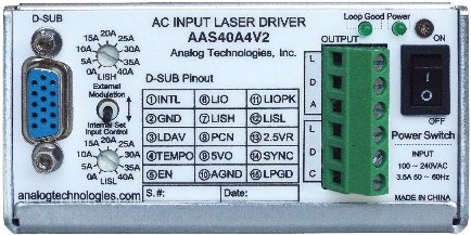
| AAS40A4V2 | Switch mode | Constant current | AC | High efficiency | 100VAC to 240VAC | 40A | 0V to 4V | 354μAP-P | 199×99×50 |
DIP
SMT
Brick
4. Service Life
Laser drivers are designed for driving diode lasers. Diode lasers are widely used in different applications, such as optical communication, optical storage, laser printing, and lidar, etc. It requires diode lasers to run stably for a long period of time, so that laser drivers should have a long service life too. Overcurrent or overvoltage may damage laser drivers internally, thus protection circuits are needed inside the laser driver to extend their service lives.
From the above introduction, you may be clearer about how to choose an off-the-shelf laser driver or design one by yourself.