This article is from Photonics Online.
Chopping a laser beam is often a necessary practice. For a diode laser, it is much simpler and less costly to chop the beam electrically, rather than mechanically. The output laser beam power, PO, versus the laser diode input current, ILD, characteristics are shown in Fig. 1.
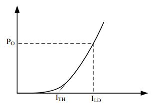
Fig. 1 — Output Laser Beam Power vs. Laser Input Current
In this figure, PO is the optical output power of the laser diode; ILD is the laser diode input current; ITH is the so-called threshold current of the laser diode. The laser diode only emits laser beam when the input current exceeds this value; otherwise, it will emit a weak, non-laser light.
1. How to Chop a Laser Beam at High Speed
Conventionally, a simple way to chop a diode laser is to inject a normal operation current to the laser diode to turn the laser on, and then shut off this current to turn off the laser. This approach is simple, but the rise time is not minimized for two reasons:
A. The laser driver is turned off during the off period, and it takes time for the laser driver to turn on. For example, the laser driver ATLS2A201D has a turn-on time delay around 1ms (see τ1 in Fig. 5).
B. Since the laser forward voltage goes to zero during the off period, when the laser is turned back on, it takes an extra time (see τ2 in Fig. 5) for the laser diode to swing its forward voltage from zero to the normal forward voltage value — usually between 1.5V to 4V, depending on the wavelength of the laser diode.
To eliminate the above-mentioned delays, the diode laser can be chopped in this way: Always keep the laser current on. As shown in Fig. 1, every diode laser has a threshold value. To “block” the beam, just lower the current to a value below the threshold. In this scenario, the diode stops emitting the laser beam, but the current keeps flowing; thus, the laser diode voltage is still around the normal forward voltage value, and the laser driver is still working, as opposed to being shut off in the conventional way. To turn on the laser, increase the current value above the threshold, and the laser will emit laser beam. There is no delay for turning on the laser driver, nor is there a delay for the laser diode to swing its forward voltage from zero to the normal forward voltage value.
To see the differences between these approaches, let us study two real examples. Fig. 2 shows a schematic implementing the conventional approach, where an electronic switch toggles the LIS port by a control signal CNT(t), between 2 voltage levels: VH and zero. The VH is set by W1, 2 corresponding to the normal operation current, to turn the laser on. The zero value corresponds to zero current at the output, and the laser is therefore turned off by stopping the laser current.
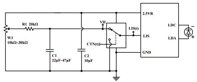
Fig. 2 — Schematic for the Conventional Laser Chopping Implementation
Figure 3 shows the schematic for the 2nd approach, in which the laser current setting port, LIS, is toggled between 2 non-zero values: VH and VL. The former is corresponding to the normal operation current to turn the laser on; the latter corresponds to a current value below the threshold, which is low enough to stop the laser beam, but high enough to keep the laser driver on to eliminate τ1 and the laser diode is biased by the normal forward voltage to eliminate τ2.
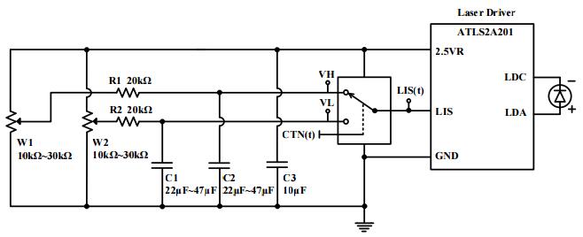
Fig. 3 — Schematic for the High Speed Laser Chopping Implementation
Figs. 4 and 5 show the actual waveforms taken from the circuit shown in Fig. 2. Notice that at rising edge of the input signal LIS(t), the corresponding output voltage at the LDA pin, LDA(t), has one delay, τ1, which is caused by laser driver’s turning on time. There is another delay, τ2, between the start rising point in LDA(t) to the start rising point of LIO(t), and this delay is required for the laser driver output to swing from zero voltage to laser diode’s normal forward voltage. The laser driver used for the test was ATLS2A201, made by Analog Technologies, Inc.
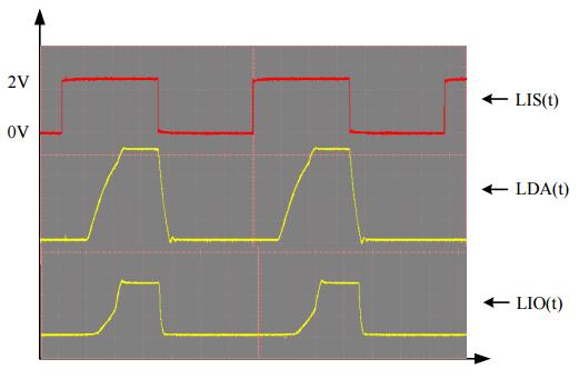
Fig. 4 — Waveforms Taken from the Conventional Laser Chopping Circuit
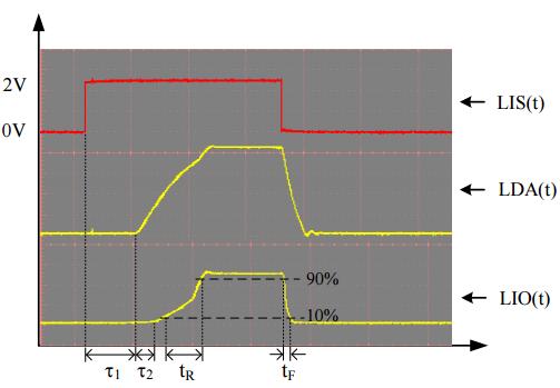
Fig. 5 — A Close-up of the Waveform in Figure 4
Fig. 6 shows the same set of waveforms, but taken from the circuit in Fig. 3. Since the laser driver was kept on all the time, and the laser diode has been biased by the normal forward voltage, the two delays seen in Fig. 5, τ1 and τ2, have been eliminated.
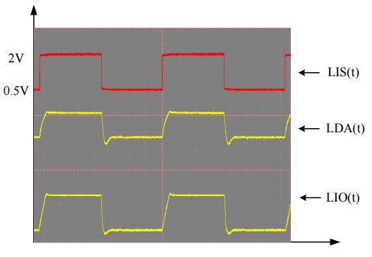
Fig. 6 — Waveforms Taken from the High Speed Laser Chopping Circuit
2. How to Chop a Laser Beam with Low Noise
Very simple: decouple the VH and VL voltage by using the capacitors — C1 and C2, respectively — to filter out the noise generated by the voltage reference, the potentiometers W1 and W2, and the resistors R1 and R2. The square-wave signal, LIS(t), at the current-setting input pin LIS, is a noise-free clean square-wave (see Figs. 2 and 3).
--------------
About The Authors
Gang Liu, Ph.D., President and Chief Design Engineer of Analog Technologies, Inc. (ATI), has been designing laser drivers and TEC controllers, and managing the company, ATI, in the past 19 years.
Nan Shi, Director of Technical Writing and Marketing Group of ATI, has been writing technical documents related to laser driver and TEC controller for 7 years at ATI.
Hongtao Zhou, Director of Electronic Group of ATI, has been designing laser drivers and TEC controllers for 10 years at ATI.